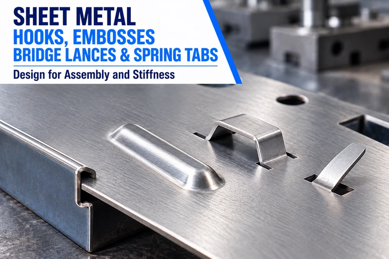
Designing a sheet metal enclosure means thinking through how the cover will fit, how internal parts will be supported, and how components will be removed for servicing. Hooks, embosses, bridge lances, and spring tabs can build some of these assembly functions into the sheet itself. The right choice depends on what each feature needs to do and how the mating parts move into place.
An enclosure cover can slide under hooks at one end, lower onto its supports at the other, and then be secured against withdrawal by a latch or screw. An internal bracket can slide through formed bridges before being secured at the end. To assess these features, consider their geometry, the assembly movement, and the surfaces that carry the load. Figure 1 shows the cover assembly before the following sections examine individual features.
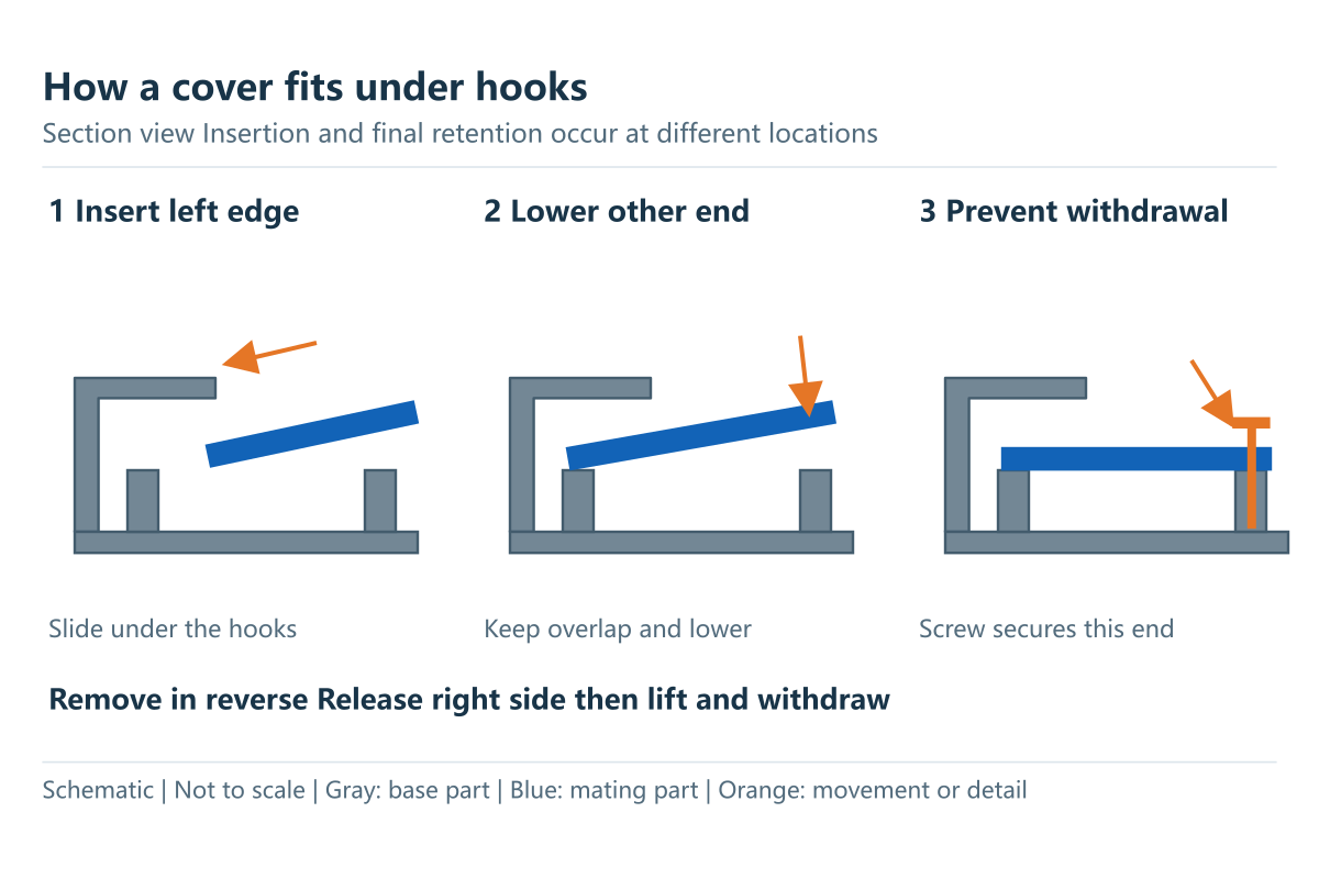
Local cutting and forming can build attachment, guidance, preload, spacing, or stiffening into the sheet itself, reducing the need for some separate components. Hooks, embosses, bridge lances, and spring tabs serve different purposes. They may also be used alongside knockouts and simple pivot connections. Start with the movement or function the feature must provide, then check the material, tooling, and dimensional relationships.
The illustrations explain structural relationships and do not represent a confirmed customer project. Dimensions are either explicitly assumed calculation examples or published tooling examples with stated material conditions. Use them to understand the design checks; confirm the final part against its drawing, manufacturing route, and assembly requirements.
How Hooks Retain Parts and Resist Withdrawal
Separate the Supporting Hook from the Retaining Dimple
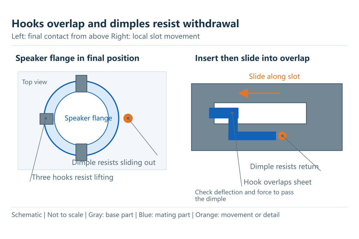
When a small speaker mounts to an enclosure panel, its outer flange can fit under several hooks. The hooks support the flange and resist lifting, while a dimple or stop in the panel restricts sideways withdrawal. Different contact surfaces constrain different movements, so each hook does not have to provide restraint in every direction.
Another arrangement inserts a hook into a rectangular slot and then slides it into an overlapping position. A dimple near the slot can resist insertion and increase resistance to sliding back. If the joint snaps over the dimple, provide a path for recoverable deflection and check the insertion and removal forces. A dimple taller than the available gap does not, by itself, establish a reliable latch.
Use Lead Ins and Additional Support for Different Purposes
A sloped hook entrance and a chamfered mating slot help the parts align and reduce edge collisions. Once assembled, defined overlapping surfaces must carry the load and resist separation. The connecting strip in Figure 3 is one way to add support and change the loading at the hook root and free end. Whether it reduces opening deformation depends on its position, cross section, and the direction of the external load.
An edge hook may be suitable for press brake forming if tool access, bend length, and radius permit. A hook inside the panel generally requires local cuts and forming tooling. Some tools cut and form in one stroke; other geometries need a prepared opening. For small quantities, consider available form tools or a dedicated small tool rather than assuming that a progressive die is necessary.
Calculate Hook Clearance from Defined Surfaces
Assume the bare part has a clear height of 1.20 mm between the underside of the hook and the upper surface of the base sheet. If the inserted sheet is 0.80 mm thick before coating, the nominal total clearance through the thickness is 0.40 mm. This difference describes the geometric allowance in this example; it is not a recommended clearance for every hook.
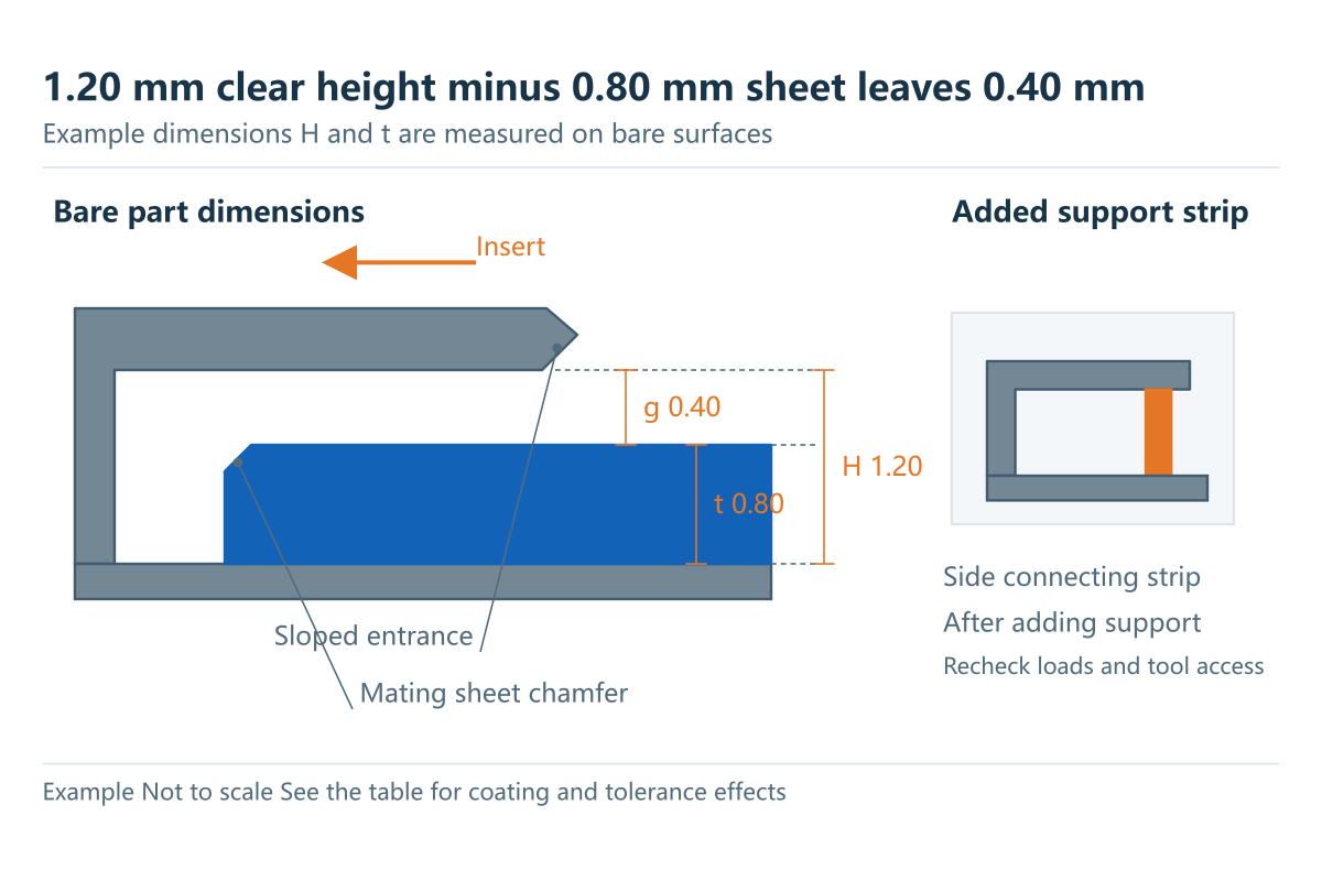 If the base contact surface, the underside of the hook, and both faces of the inserted sheet are coated, all four facing surfaces consume that clearance. The following table uses the same assumed dimensions to show why subtracting 0.80 from 1.20 is not enough. Every coating thickness is an assumed calculation input, not a coating specification. Geometric tolerances, burrs, and angular errors require separate allowance.
| Example condition | Clearance calculation mm | Meaning |
|---|---|---|
| Nominal bare dimensions | 1.20 − 0.80 = 0.40 | Coating and size variation excluded |
| Four facing surfaces each gain 0.05 | 1.20 − 0.80 − 4 × 0.05 = 0.20 | Coating reduces the finished allowance |
| H = 1.20±0.10 t = 0.80±0.05 Each surface gains 0.05 | Minimum 1.10 − 0.85 − 0.20 = 0.05 Maximum 1.30 − 0.75 − 0.20 = 0.35 |
Limits for the stated inputs only |
| Minimum H and maximum t Each surface gains 0.08 | 1.10 − 0.85 − 4 × 0.08 = −0.07 | Theoretical interference Revise fit or process |
Check insertion at the minimum clearance and acceptable movement and overlap at the maximum clearance. Where preload is required, provide controlled elastic deflection and verify insertion force, retention, and permanent deformation. Changing every sliding fit into an interference fit and forcing the parts together is not a substitute for these checks.
How Long Hooks Retain Cables and Harnesses
A long formed hook can accept a flat cable or harness from the side. A lead in helps the cable slide beneath it, and the long strip restricts lifting. Protecting the insulation is the first concern: inspect the actual cut edges, burrs, and sharp corners at cable contact points. Provide space appropriate to the cable dimensions, bending, and vibration.
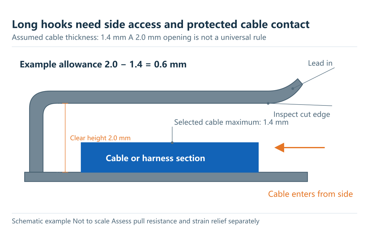
For example, a proposed hook may have a clear height of 2.0 mm, while the selected flat cable has a maximum thickness of 1.4 mm at that location. The static geometric allowance is 0.6 mm. This illustrates a check for a selected cable; it does not make 2.0 mm a universal cable clearance. If the assembly needs clamping, pull resistance, or strain relief, assess cable ties, edge protection, or a dedicated retainer rather than relying on an unverified sheet edge to provide every function.
How Embosses Provide Location Spacing and Stiffness
The Contact Surface Determines the Function
An emboss is a raised feature formed in the sheet. A small dimple can act as a locating stop for a sliding part. A flat topped emboss can support a PCB above the base panel, while an elongated emboss can form a stiffening rib. These related names do not imply the same cross section or load path.
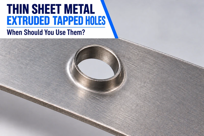
At a PCB mounting point, separate the support height from the screw connection. A flat topped emboss can space the board above the panel without providing a usable thread. If a threaded mounting point is also needed, consider an extruded and tapped hole in the emboss and verify effective thread engagement, screw tip clearance, and space beneath the board. Separate supports such as self clinching standoffs are another option. See our guide to extruded tapped holes in thin sheet metal for the thread connection checks.
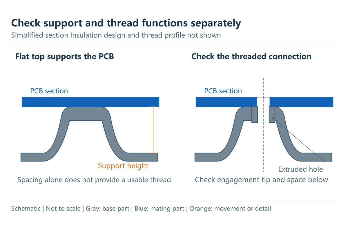
Emboss height depends on material flow, wall shape, transition radii, sheet thickness, and tooling. A wall angle alone does not establish a formable height. Define the datum for the support surface on the drawing. Also check the recess on the reverse side, local thinning, surrounding panel distortion, and interference with nearby holes and bends.
Assess Rib Position Together with Its Cross Section
When a large cover or the middle of a handle deflects under load, compare an edge flange with a rib formed inside the panel. The flange changes the edge section; the rib creates a local raised profile where needed. Its direction, length, end transitions, and relationship to the supports affect which deformation it resists. A general statement that it increases strength does not describe that behavior adequately.
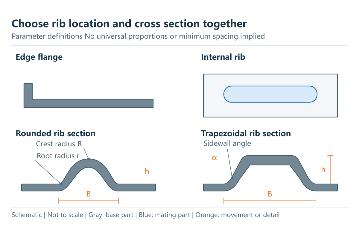
Common sections include rounded and trapezoidal ribs. Specify width B, height h, crest and root radii, and sidewall angle, and clarify whether each dimension describes a finished surface, a theoretical profile, or a tool. Evaluate the transitions, local stretching, and panel distortion near edges for the actual material and tooling.
Published tooling examples help show how these dimensions relate. The following table takes the stated materials and dimensions from three companion tool drawings and converts inches to millimeters. It illustrates specific combinations of material, thickness, and tooling. These are not universal minimum dimensions or a list of Tongyong tooling. Check each companion drawing for the endpoints used to define its listed width.
| Tool example | Drawing material and thickness | Listed width mm | Raised height mm |
|---|---|---|---|
| R11 | Aluminum 1.016 mm | 5.26 from 0.207 in | 0.89 from 0.035 in |
| R21 | Cold rolled steel 1.245 mm | 4.50 from 0.177 in | 0.99 from 0.039 in |
| R31 | Stainless steel 1.499 mm | 4.62 from 0.182 in | 1.14 from 0.045 in |
This table does not establish a material grade, condition, or complete tolerance scheme; confirm those before selecting a tool. Check tool clearance separately from the finished rib height so later operations do not flatten an existing feature.
How Bridge Lances Guide Mating Parts
A bridge lance is a locally cut and raised strip that remains attached to the parent sheet at both ends. It can create a passage for a cable tie or mating sheet, and repeated bridges can provide guidance. Its loading and deflection differ from those of a tab with one free end.
In the left detail of Figure 7, the mating sheet enters beneath the bridge and moves to its locating surface. A screw or separate latch then prevents withdrawal. This separates guidance from final retention. Controlled contact pressure may be possible beneath a bridge, but the entrance must allow insertion and the maximum clearance must not permit unacceptable movement.
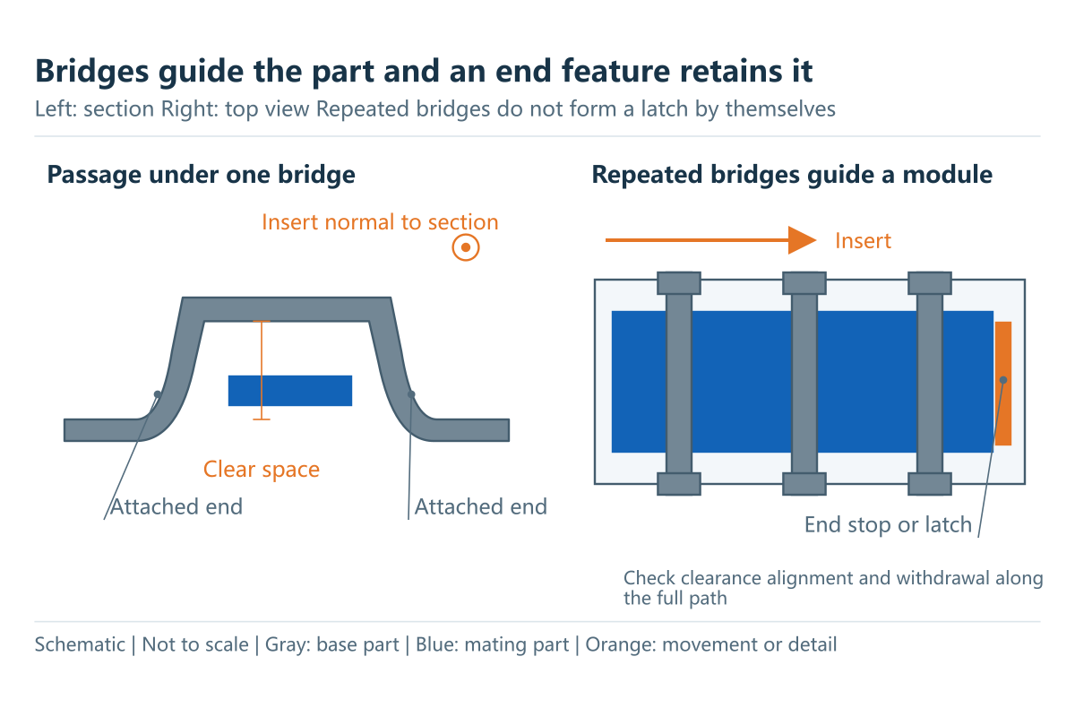
When several bridges guide an internal module, check their clear heights and lateral positions together with the straightness of the module edge. Passing through one cross section does not prove that the whole insertion path is clear. With a combination of bent rails and local bridges, include bend springback, coating, and the final insertion direction in the assessment.
State whether the drawing controls the clear space under the bridge or its overall height, and identify the forming direction. Check whether the selected tool requires prepared cuts, can cut and form in one stroke, and has sufficient space near bends and openings. Similar looking bridges do not necessarily share one spacing rule.
How Spring Tabs Provide Preload and Release
Check the Free Working and Maximum Depressed Positions
Cutting three sides of a narrow strip while leaving its root attached, then raising part of the strip, can create a spring tab. An installed module depresses it, and the remaining elastic deflection provides preload. If the tip also has suitable engagement geometry, the tab can latch a cover and release when pressed.
Check the free position, the working position, and the maximum depression during insertion or release separately. Free height affects initial contact, the working position affects preload, and maximum depression determines whether the permitted deflection is exceeded. Figure 8 also shows a mechanical stop to limit overtravel. It must allow enough movement for normal disengagement before stopping further travel.
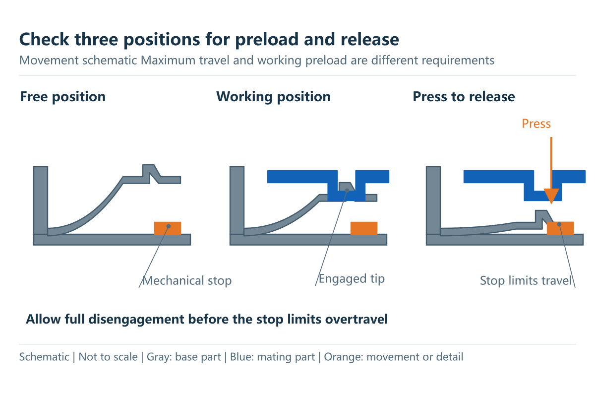
Material grade and condition, thickness, effective length, root transitions, and cut edge quality all affect the tab. Returning after one press does not prove a specified cycle life. Frequent servicing, greater travel, or tighter force requirements may favor a separate spring clip over a tab cut from the enclosure material. A replacement material of the same thickness still requires a review of stiffness, yielding, springback, and actual operating force.
Compare Length and Thickness at the Same Deflection
To illustrate the effect of geometry, model the tab as a straight cantilever with uniform width and thickness, a fully fixed root, and an end load within the small deflection linear elastic range. Assume an elastic modulus E of 200 GPa, width b of 6 mm, and an imposed tip deflection of 0.30 mm. The modulus is only an example input; it is not a value for every steel, a strength limit, or a fatigue life rating.
F = (E × b × t³ × δ) / (4 × L³)
Here F is the force required for the imposed tip deflection, L is effective length, t is thickness, and δ is tip deflection. The equation follows from the small deflection relation for an end loaded cantilever and the second moment of area of a rectangular section. The MIT beam theory reference at the end provides the basis.
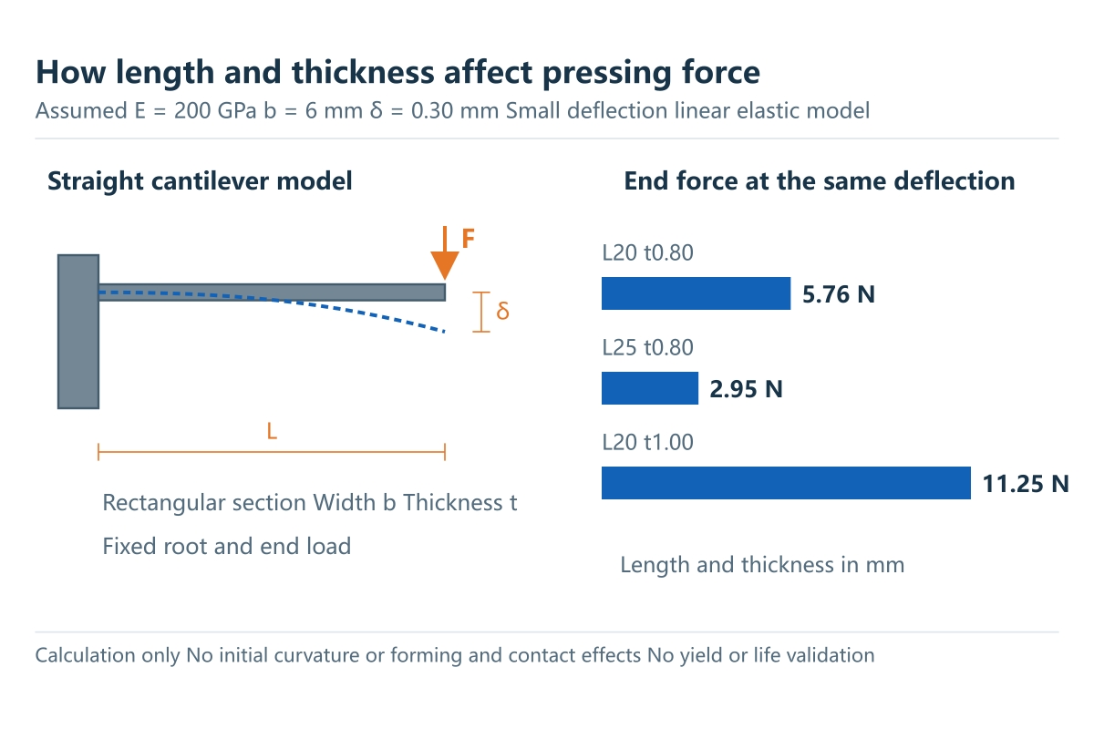
| Example | Effective length L mm | Thickness t mm | End force at 0.30 mm deflection N |
|---|---|---|---|
| Baseline | 20 | 0.80 | 5.76 |
| Longer effective section | 25 | 0.80 | 2.95 |
| Greater thickness | 20 | 1.00 | 11.25 |
For the same tip deflection, greater thickness substantially increases the required force, while greater effective length reduces it. A real formed tab may have initial curvature, sloped contact, a moving contact point, and large deflection. Do not use the table directly as a latch force specification. Check yielding for the actual material, root stress concentration, springback, and repeated operation.
Distinguish Half Shear Locators from Knockouts
Half shearing locally displaces partially sheared material without removing it completely, and can produce a locating or supporting feature. A knockout serves a different purpose: it leaves a removable piece in an electrical box or enclosure until an opening is needed for a fitting or another interface. Half shear and knockout are not interchangeable terms.
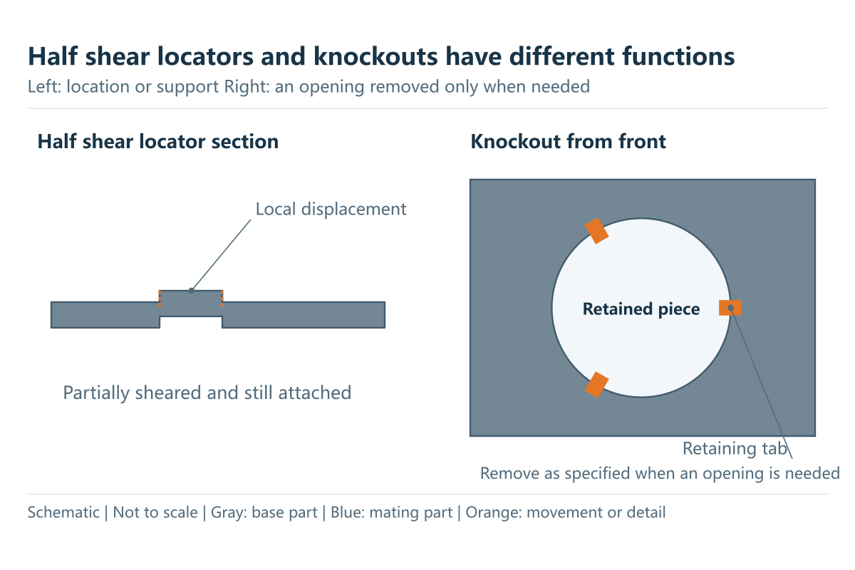
One way to make a knockout is to cut around its perimeter while leaving retaining tabs. The tabs must keep it in place during transport, coating, and normal handling while allowing removal by the specified method when an opening is needed. Their number, width, and position depend on sheet thickness, knockout size, removal direction, and required retention. A 1 mm tab width is not a universal rule.
Size the opening from the selected fitting or grommet's actual mounting requirements rather than its nominal trade size alone. After removal, address the remaining edges and clear loose metal from the enclosure. Even an intact knockout does not, by its appearance alone, establish dust, water, or electromagnetic shielding performance.
How Formed Features Can Support a Simple Pivot
For a simple folding cover or a lightly loaded lever, a raised feature and a mating hole or opening may be considered as a pivot. The emboss must do more than locate the part: the connection needs support, restraint against axial separation, and clearance throughout its rotation. Figure 11 shows a concept, not a bearing arrangement with verified load capacity.
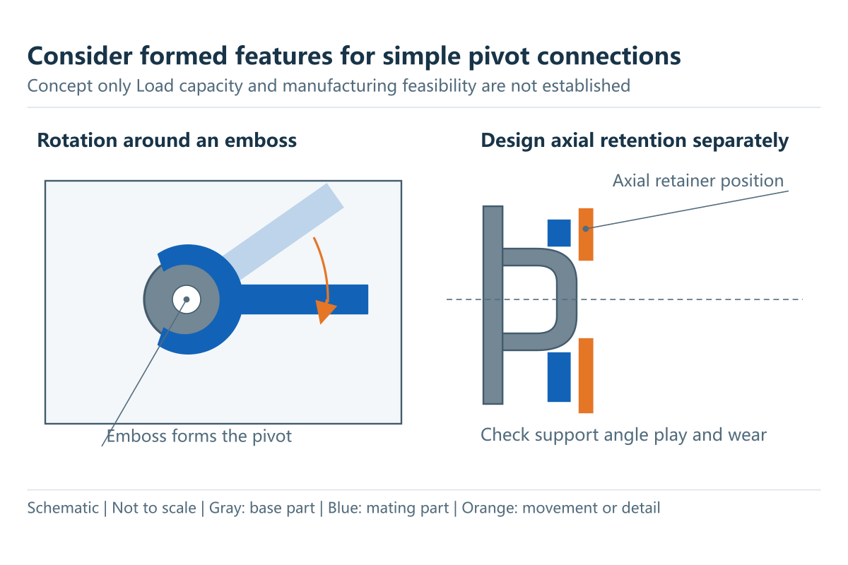
A separate pin, rivet, or standard hinge may also be suitable. Forming hinge knuckles from the sheet requires checks of thickness, internal curl diameter, pin fit, and forming operations; it is a different structure from the embossed pivot in Figure 11. At higher quantities, compare the tooling investment with possible assembly savings. For smaller quantities or tighter clearance and life requirements, compare separate hardware options.
Do not assume every formed pivot is imprecise, or that rotation alone makes one a substitute for a precision shaft. Define permitted radial and axial play, retention, operating torque, travel stops, and wear after repeated operation, then choose the manufacturing and validation method.
Carry the Design into Drawings and Representative Samples
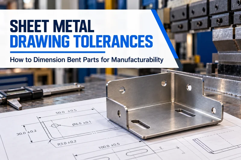
After choosing the geometry, identify the material grade and condition, forming and insertion directions, measurement surfaces for functional dimensions, and treatment of critical cut edges. For spring tabs and knockouts, define working conditions and functional acceptance criteria. Relate tolerances to the actual contact surfaces; our sheet metal drawing tolerances guide explains the broader drawing considerations.
Validate the complete sequence from insertion and seating to retention, release, and removal. For repeated operation, use samples representative of the intended material, cut edges, forming, and finish. Plan support and handling after forming so later bending, blanking, or clamping does not damage small raised features. See our sheet metal design guidelines for the overall bend, hole, and fastener layout.
References
Wilson Tool — Design Basics of Lance & Forms Lancing and forming of tabs and bridges with tooling considerations
Protolabs — Stocked Punch Form Tooling Emboss rib and half shear categories with companion tool drawings
Lee Spring — Flat Springs Material force deflection and repeated operation considerations for flat springs
MIT OpenCourseWare — Euler Bernoulli Beams David M Parks 2.002 Lecture 2 Basis for the end loaded cantilever calculation
Wilson Tool — Electrical Knockouts Electrical knockout use and retaining tabs
Wilson Tool — Hinge Tool Manufacturing route for hinge knuckles formed from sheet
FAQ
Can Hooks and Bridge Lances Replace Screws Completely
They can eliminate some fasteners, but first check which movements each feature restrains. A bridge may only guide a part, while a hook may prevent lifting without preventing withdrawal. Where vibration, pull loads, servicing, or sealing matter, verify retention and release in the complete assembly. Fewer components alone do not establish a suitable replacement.
Do Small Batches Require a Progressive Die
Not necessarily. Compare edge bending, available punch form tools, dedicated small tools, and separate hardware. A special tool for a local tab or bridge is not the same as a complete progressive die. Provide material, thickness, forming direction, quantity, and functional dimensions so the manufacturer can assess tool access, the operation sequence, and setup cost.
Can Every Hook Use a 0.4 mm Clearance
No. The 0.4 mm value here comes from two specific bare part dimensions. Sheet thickness variation, forming tolerances, and coatings on the facing surfaces change the finished allowance. Verify insertion at minimum clearance and movement and retention at maximum clearance. If preload is required, also check actual deflection and force.
Does a Laser Cut and Hand Bent Prototype Validate Stamped Production
It can help check space, insertion paths, and general fit, but it does not fully represent stamped roots, cut edges, springback, local thinning, or forming consistency. Samples used to approve production should represent the intended route, particularly when checking spring force, dimple engagement, and distortion around ribs.
Does an Intact Knockout Guarantee Enclosure Protection
No. Perimeter cuts, retaining tabs, seams, and finishing can affect the complete enclosure. Define the required protection and electrical performance, then validate the assembled enclosure and its interfaces. After removing a knockout, the selected fitting, grommet, or closure must also suit the final requirements.