Article Summary
Enclosure covers and internal brackets show why thin sheet can need more thread engagement. Learn when extruded tapped holes are worth evaluating and what to check before production.
An electronics enclosure may need a removable cover for servicing and internal brackets to secure its modules. These screw connections often rely on thin sheet metal. A screw may turn into the hole, yet the sheet thickness leaves only a short length for the internal thread. The nominal thread size alone does not show whether the joint can be tightened and perform as required.
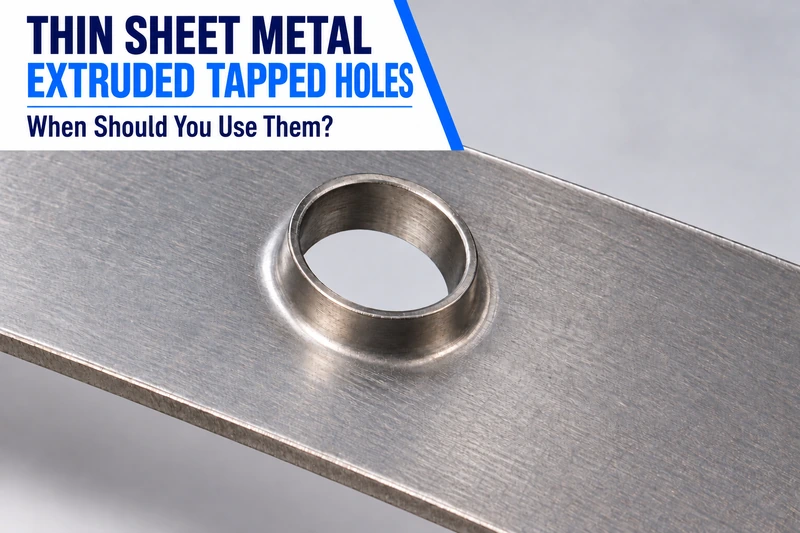
Extruded tapped holes in sheet metal are one option worth evaluating. Material around a hole is formed into a projecting collar, and an internal thread is then produced in that collar. This can increase effective thread engagement: the axial length over which the screw and the complete internal threads actually mate in the assembled joint. The choice still depends on the material, hole geometry, screw, and assembly requirements. Removable enclosure covers and internal mounting brackets provide useful examples of how those factors affect the decision.
Identify Which Part Needs the Threaded Hole
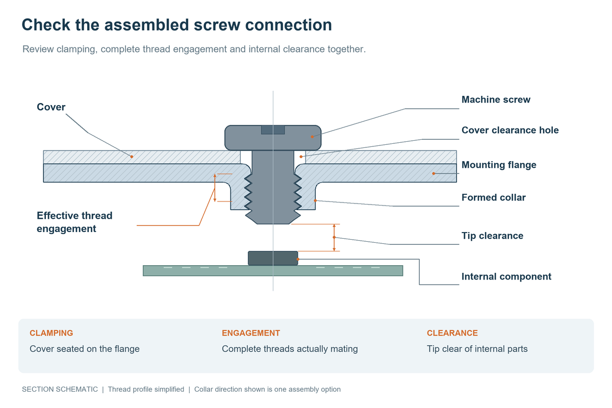
Consider a removable enclosure top cover. A screw can pass through a clearance hole in the cover and engage a threaded hole in a mounting flange or tab on the enclosure body. The cover is clamped in place; the sheet underneath provides the internal thread. Keep those two functions clear when evaluating an extruded tapped hole. The clearance hole in the cover has a different purpose.
If the mounting flange is too thin, tapping it directly may not provide enough effective thread engagement. Forming a collar can increase the wall length available for threading, but the collar projects to one side of the sheet. If it faces into the enclosure, check for interference with circuit boards, wiring, and other components. If it faces the cover, check that the cover can still seat properly.
An internal module bracket raises similar questions. Its threaded holes must align with the module's mounting holes, and the screws must clamp the intended mating surfaces. Check screw length, the location of thread engagement, and tip protrusion together. A screw that contacts an internal component before clamping the joint can give a misleading impression that the assembly is tight.
How a Formed Collar Provides More Length for Threads
In cross section, the wall length of a plain hole is largely limited by the original sheet thickness. Hole extrusion forms the surrounding material into a collar that projects from one side. Producing an internal thread in this collar creates an extruded tapped hole, with a threaded region that can extend beyond the original sheet thickness.
A typical route involves a pilot hole, collar forming, and threading. The pilot hole prepares material for the forming operation; forming creates the collar; threading produces the internal thread that mates with the selected screw. Specialized tooling can combine some actions, so these functions do not always require separate machines or setups.
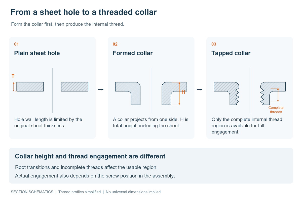
After the collar is formed, the internal thread can be produced in different ways. A cutting tap removes material to create the thread. A forming tap displaces material plastically and produces no cutting chips. Thread forming is a separate operation from forming the collar around the hole. Cutting and forming taps have different requirements for hole size and material suitability. Establish those requirements for the specific material, thread, and tapping method rather than using the same prepared hole size for both.
A related approach uses a suitable screw to cut or form its mating thread during assembly in a formed hole that has not been fully threaded beforehand. Specify this separately from a machine screw connection with a preproduced internal thread. Drawings and purchasing requirements should identify which approach is intended; specifying only a formed hole leaves the threading requirement incomplete.
When an Extruded Tapped Hole Is Worth Evaluating
Consider an extruded tapped hole when direct tapping provides insufficient engagement and the design calls for a threaded mounting point formed from the sheet itself. There must be room for the projecting collar, the material must suit the forming operation, and the tooling must be able to reach the hole.
The connection's job also matters. A light cover, an internal module, and a bracket carrying a larger external load may need different hole structures even if they use the same nominal thread. If the connection will be opened regularly for servicing, include that requirement in the engineering review.
| Connection option | When to evaluate it | What to confirm first |
|---|---|---|
| Directly tapped sheet | The original sheet thickness can provide sufficient effective thread engagement | Complete thread length and joint load requirements |
| Extruded tapped hole | More engagement is needed, using the sheet itself to form the mounting point | Material formability, collar quality, and clearance on the projecting side |
| Self-clinching nut | A separate threaded element is preferred and press installation is accessible | Compatible sheet hardness and thickness, mounting hole, and press tooling |
| Blind rivet nut | The threaded element must be installed from one side | Grip range, installation tool access, and space for deformation on the back side |
Self-clinching nuts and blind rivet nuts use different retention mechanisms and have different selection requirements. A self-clinching nut locks in place as sheet material flows into its retaining features during pressing. Common blind rivet nuts grip the sheet through deformation of the nut body during installation. Changing between these options requires another check of the mounting hole, sheet thickness, and available space, even if the thread size stays the same.
Check Collar Height and Effective Engagement Separately
Total collar height is not the same as effective thread engagement. The transition radius at the root, incomplete threads at the opening or end, and the screw's end geometry can all affect the length that actually engages. Define the start and end points of any height dimension on the drawing. Projection measured from a sheet surface and total height including the sheet thickness are different dimensions.
Review a section through the hole alongside a section through the assembled screw connection. Once the cover is seated, how much of the screw's complete external thread mates with complete internal threads? Does that length meet the joint requirements? Can the screw head clamp the cover properly, and does the tip clear the circuit board or other components behind it? These checks tell you more than collar height alone.
Engaged thread count alone is not proof of reliability. Material strength, thread condition, diameter, and actual engagement length all affect joint capacity. Tightening requirements also depend on friction, coatings, and lubrication. A general screw torque chart does not establish the torque capacity of a thin collar's internal thread.
Details to Define Before Manufacturing
Distinguish the Extrusion Pilot Hole from the Tapping Hole
The pilot hole prepares the sheet for collar forming, and its size affects whether sufficient material can form the required collar. The tapping hole serves the subsequent threading operation. These are different requirements; do not assume the same diameter applies to both. Define the finished thread, hole location, forming direction, and final geometry on the drawing. Engineering and manufacturing can then establish the pilot hole size, forming tooling, and tapping route.
If the drawing controls dimensions at intermediate stages, identify the stage explicitly so that the hole before forming is not mistaken for the hole required before tapping. Changes in material grade or condition, sheet thickness, or target hole size also require a review of the forming preparation.
Specify Which Side the Collar Projects Toward
Show the collar direction relative to the assembly surface on the drawing or section view. On an enclosure mounting flange, check whether the collar prevents the cover from seating, intrudes into the component space, or obstructs screw insertion. If the joint needs a countersunk or locally recessed seat, check that geometry separately. The appearance of the hole alone does not establish that a screw head will sit flush.
Check Nearby Features and the Operation Sequence
Collar forming deforms the material around the hole. Where a hole is close to a sheet edge, cutout, another formed feature, or a bend, check the material available locally and the space needed by the tooling. After forming, inspect for collar cracking, excessive local thinning, and distortion of the surrounding sheet.
An existing collar can interfere with support or workholding during later bending, while bending can change nearby hole geometry. Establish the operation sequence for the final part. Our sheet metal design guidelines cover the broader considerations for bends, hole placement, and hardware layout.
Plan Threading and Surface Finishing Together
If the enclosure or bracket will be painted, plated, or otherwise finished, define how the threads will be protected, when they will be produced, and how they will be inspected. Coating inside a thread can affect screw fit. Retapping or reworking the thread afterward may remove part of its protective coating. Inspect the thread in its final delivery condition, rather than checking only whether a screw fits before finishing.
Validate the Hole and the Complete Assembly
Start with the collar and internal thread: direction, location, collar condition, and the thread dimensions required by the drawing. Thread gages used under the applicable inspection specification can check dimensional conformity. Those checks do not replace verification of the joint's load capacity and intended use.
Then assemble the cover or bracket with the selected screws, washers, and other mating parts used in the product. Confirm alignment, clamping, and clearance. Establish tightening, load, or repeated assembly tests as the product requires. Record the material, surface condition, screws, and assembly conditions so that the results can be compared meaningfully.
A prototype made from a different blank or with a substitute hole structure may demonstrate assembly fit, but it does not establish the performance of the planned production collar. Confirm the production approach with samples that represent the intended material, forming process, and threading method.
Review Your Thin Sheet Threaded Joint with Our Engineers
If you are developing an enclosure, cover, or internal mounting bracket, contact Tongyong's engineering team with your 2D drawings, 3D model, and details of the mating parts. Include the material, sheet thickness, thread specification, available assembly space, and service requirements. Our design for manufacturability (DFM) and engineering support can help review the hole geometry and manufacturing route, including whether an extruded tapped hole or another fastening approach suits the design. If your drawings are still in development, share the current structure, material, and connection requirements to start the discussion.
References
1. UniPunch — Extruded Holes Combined piercing and extrusion, and applications using suitable screws or subsequent tapping.
2. TRUMPF — Tapping Tool Internal thread forming by material displacement, as distinct from thread cutting.
3. PennEngineering — Self Clinching Technology Self-clinching retention and material and installation requirements.
4. Sherex — Rivet Nut Insert Catalog EN-RN 3/2023, printed pp. 4 and 6. Blind installation and grip range terminology; check the selected product's installation requirements.
FAQ
Can I reuse the hole when replacing a self-clinching nut with an extruded tapped hole?
The hole will usually need to be redesigned. A self-clinching nut's mounting hole is sized for retaining the fastener. An extrusion pilot hole determines how material forms the collar and its final geometry. Even if the finished thread size stays the same, reassess the surrounding material, forming clearance, and joint requirements.
Can I keep the same tightening settings after changing the screw?
Review them again. Screw length, thread geometry, coating, lubrication, and the bearing surface under the head can all affect the joint. Confirm effective engagement and clamping with the new combination, then validate its tightening requirements. Matching nominal diameter alone is insufficient.
Can I use a larger screw if the collar's internal thread strips?
A larger screw is not a default repair. The formed collar may not have enough remaining material for a larger thread. Cracks, remaining wall material, and the hole in the mating part also need review. Assess repair or replacement against the actual part condition and joint requirements; making a screw turn into the hole does not by itself restore the connection.