A sheet metal part that looks effortlessly simple in a 3D CAD environment can quickly become a complex challenge on the manufacturing floor. While software assumes perfect angles and zero material distortion, the physical reality of sheet metal fabrication introduces variables such as elastic recovery, material grain direction, and localized stress zones. When these real-world manufacturing constraints are not accounted for, bending, forming, hardware installation, and inspection become significantly more difficult.
This is where Design for Manufacturability (DFM) becomes essential. DFM acts as the critical bridge connecting your product's functional requirements with actual fabrication feasibility. At Tongyong Industries, our DFM & Engineering Support teams frequently collaborate with mechanical engineers to optimize models before production begins, ensuring that components are not only structurally sound but also efficient to produce.
How Sheet Metal Design Decisions Affect Manufacturability
Every geometric feature applied to a sheet metal model triggers a specific sequence of manufacturing events. There is a direct relationship linking your initial design choice to the fabrication difficulty, which ultimately drives the cost, lead time, and quality risk of the final product.
When an engineer specifies an unusually tight bend radius or places critical features too close to a bend line, it directly impacts bending complexity. This often forces the manufacturer to utilize specialized press brake forming techniques or custom tooling rather than standard setups. Furthermore, parts with complex, multi-axis bending sequences can create tool interference, making the component physically impossible to form without colliding with the machine.
Beyond forming, design decisions ripple into secondary operations. Unrealistic tolerance requirements drastically increase inspection difficulty, while poorly planned fastener placements can lead to severe assembly issues. By understanding how processes like laser cutting, metal stamping, and welding & assembly interact with your CAD model, designers can proactively eliminate these downstream risks.
Bend Design Considerations: Radius, Springback and Tool Access
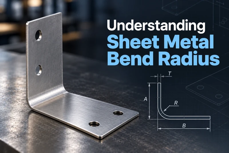
The foundation of sheet metal design lies in understanding the mechanics of a bend. Engineers must recognize the difference between the theoretical design radius in a CAD program and the actual formed radius achieved on the shop floor.
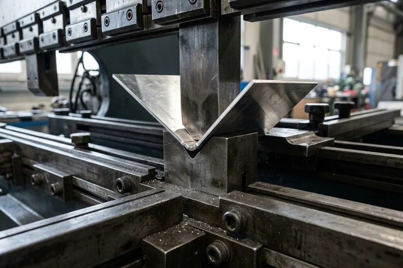
When a flat piece of sheet metal is forced into a V-die, it undergoes both tension on the outside and compression on the inside. Because sheet metal retains elastic properties, it will naturally attempt to unbend slightly once the tooling pressure is released—a phenomenon known as springback. To achieve the target angle, the operator must over-bend the material. Consequently, the actual formed radius is heavily influenced by the material’s yield strength, thickness, temper, and the specific bending method applied (such as air bending versus bottoming).
While many online resources present generic rules—such as setting the minimum bend radius to a strict multiple of the material thickness—these should not be treated as universal laws. The achievable radius depends highly on the material and tooling available. Additionally, designers must account for tool accessibility. A complex part with multiple adjacent bends may block the press brake punch from seating properly, requiring the geometry to be redesigned to allow for clear tool access.
Hole and Slot Placement Near Bend Areas
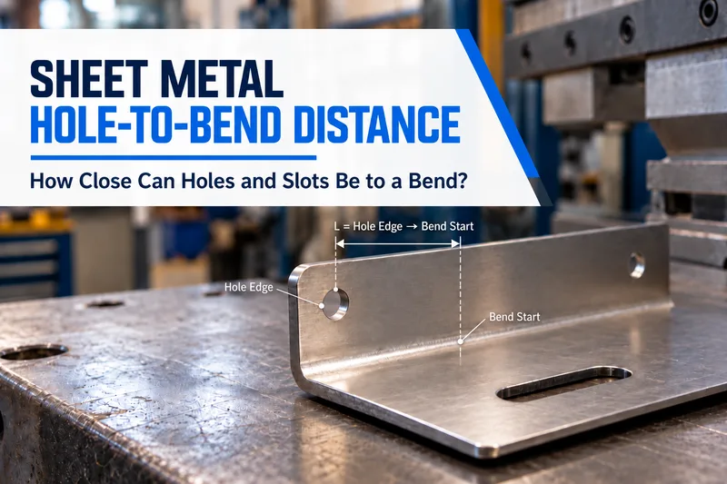
Placing holes, slots, or cutouts too close to a bend line is a frequent source of manufacturing defects. When sheet metal is bent, the material surrounding the bend line undergoes severe plastic deformation. If a hole is located within this plastic deformation zone, the tensile and compressive stresses will pull the geometry out of its intended shape.
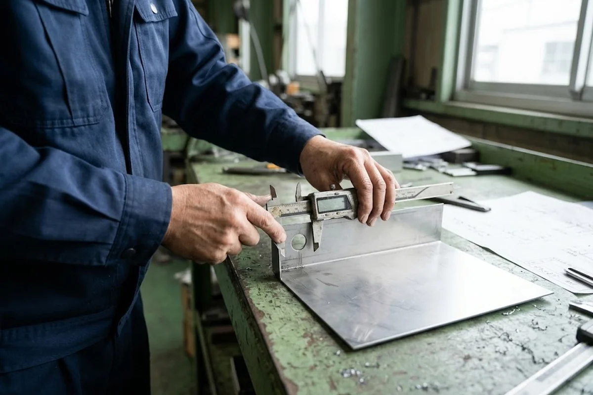
This results in hole elongation and slot distortion. A perfectly round CAD hole will stretch into an oval, which can ruin fastener clearances or prevent hardware from seating correctly. While some distortion is acceptable for non-functional weight-reduction holes, it is disastrous for functional alignment points.
Instead of relying on fixed, universal distances, engineers must evaluate the specific application. Many manufacturers use thickness-based guidelines as an initial reference, but the actual distance depends on material, tooling, bend radius, and functional requirements.
Flange Design and Press Brake Limitations
A flange geometry that is theoretically possible to draw in software may not always be practical to form on a press brake. One of the most common issues arises from minimum flange length considerations. During the bending process, the sheet metal must span across the open width of the V-die to be properly supported while the punch pushes it downward.
If a flange is designed too short, it will slip into the die rather than forming a clean angle. The minimum required length is dictated by the specific V-die width required for the material thickness. Furthermore, designers must evaluate tool interference on consecutive flanges, such as narrow U-channels. If the distance between two opposing flanges is narrower than the width of the press brake punch, the part cannot be formed in a standard bend sequence. Evaluating the step-by-step bend sequence during the CAD phase helps avoid geometry that structurally locks the tooling.
Designing for PEM Fasteners and Hardware Installation
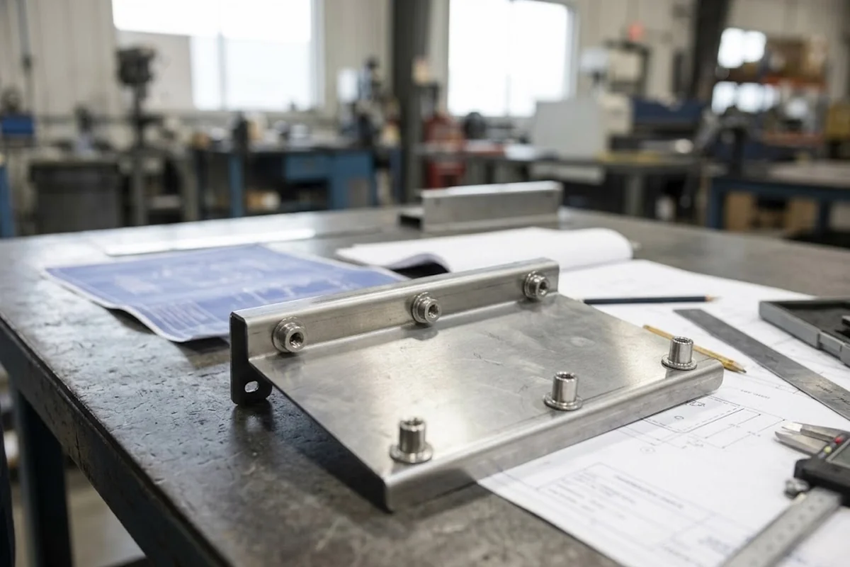
Integrating self-clinching fasteners, such as PEM nuts and standoffs, requires strict adherence to hardware-specific design rules. For a self-clinching fastener to anchor properly, the host sheet metal must displace and flow into the undercut of the fastener's shank.
According to technical specifications such as the PEM fastener design guide, the host material generally needs to be softer than the fastener itself; otherwise, the fastener will crush before it clinches. Engineers must also carefully calculate the edge distance. If a fastener is pressed too close to the edge of the sheet metal, the displaced material has nowhere to go but outward, causing the edge of the part to bulge or warp.
Surface finishing must also be considered during the hardware design phase. If parts are designated for powder coating, plating, or painting, the dimensional build-up of the finish can alter the hole size prior to installation, or clog the internal threads of the fasteners if installed beforehand.
Sheet Metal Tolerances and Functional Dimensions
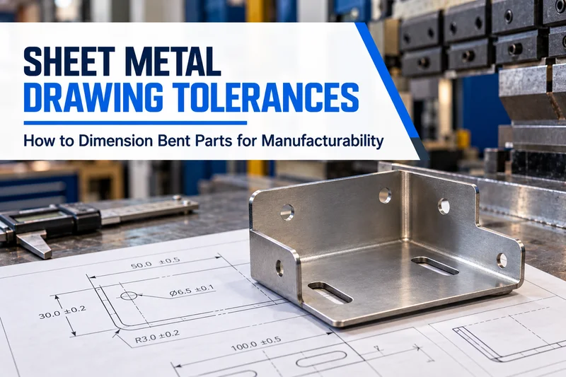
Sheet metal components exhibit completely different tolerance behaviors compared to rigid CNC machined parts. A flat profile created via laser cutting can hold exceptionally tight tolerances. However, once that part moves to press brake forming, angular variations are introduced.
In a formed part, tolerances accumulate with every subsequent bend. Dimensioning a feature across multiple bend lines forces the manufacturer to control the stacked angular errors of all preceding bends, which drastically increases cost and inspection effort. To optimize a design, engineers should establish a functional datum structure. Dimensions should be tied to the features that matter most for final assembly, avoiding unnecessary tight dimensions on free edges or non-mating surfaces. Following standards such as ASME Y14.5 Geometric Dimensioning and Tolerancing ensures that the inspection conditions align with the functional intent of the part, rather than over-constraining the manufacturing process.
Sheet Metal DFM Checklist Before Fabrication
Before submitting CAD files for quotation and fabrication, engineers can use this initial checklist to identify and resolve common manufacturing risks.
| Design Consideration | Manufacturing Risk | Better Practice |
|---|---|---|
| Bend radius | Cracking or inconsistent forming | Consider material properties and tooling limitations |
| Hole near bend | Hole distortion and elongation | Evaluate the plastic deformation zone |
| Short flange | Tooling interference or slipping into the die | Check press brake V-die requirements |
| Tight tolerances | Higher inspection effort and part rejection | Apply strict tolerances only to functional features |
| PEM installation | Poor retention or edge bulging | Follow specific fastener edge distance requirements |
References & Sources
- ASME Y14.5 — Dimensioning and Tolerancing. American Society of Mechanical Engineers. Serves as the foundational engineering standard for establishing datum structures and functional GD&T practices.
- PennEngineering PEM® Fastener Design Manual. Provides strict industry guidelines for self-clinching fastener selection, material hardness compatibility, and edge distance requirements.
- Industry DFM References: For further understanding of typical manufacturing capabilities, resources such as the Protolabs Sheet Metal Design Guide and Xometry Sheet Metal Design Guide provide useful baseline limits for standard fabrication equipment.
Ready to turn your optimized designs into reality? Learn more about our comprehensive sheet metal fabrication services and see how Tongyong can support your next manufacturing project.
FAQ
How close can a hole be to a sheet metal bend?
Many manufacturers use thickness-based guidelines as an initial reference, but the actual safe distance depends on the material, tooling, bend radius, and the functional requirements of the hole. The goal is to keep the hole entirely outside the plastic deformation zone to prevent elongation.
What factors affect sheet metal bend radius?
The actual achieved bend radius is determined by a combination of the material's yield strength, the sheet thickness, the material temper, and the forming method used (such as air bending). Because sheet metal springs back after forming, the punch must over-bend the material.
Why do sheet metal parts change dimensions after bending?
Bending sheet metal stretches the material on the outside of the curve and compresses it on the inside. The neutral axis (the plane where the material neither stretches nor compresses) shifts depending on the material and tooling. This shift, calculated using a K-factor, alters the total flat length required to achieve the final formed dimensions.
How should PEM fasteners be considered in sheet metal design?
Designers must ensure the host material is softer than the fastener hardware to allow proper clinching. Additionally, strict edge distance guidelines must be maintained to prevent material bulging, and the pre-punch hole size must be precisely matched to the fastener specifications.
Why are sheet metal tolerances different from machined part tolerances?
Unlike rigid blocks of metal in CNC machining, sheet metal is flexible and formed using localized pressure. Each bend can introduce a slight angular deviation. When a part features multiple bends, these deviations stack up, meaning dimensions measured across multiple bends require looser tolerances to be practically manufacturable.