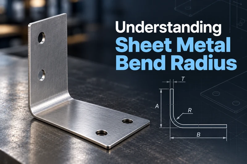
A bend radius may look like a simple R value on a sheet metal drawing, but the formed result is not always as straightforward as the CAD model suggests. In air bending, the final inside radius is influenced by the V-die opening, material thickness, material condition, bend angle, and springback. The design radius, the tooling geometry, and the radius measured on the finished part do not necessarily match.
The first question is whether the radius actually matters to the part’s function. If it affects assembly clearance, interference with a mating part, sealing, fatigue, or appearance, the finished requirement should be defined clearly. If the radius is only a CAD default with no functional effect, an unnecessarily tight callout may force the supplier to change tooling or move away from a stable bending setup for no real benefit.
Why the Radius on the Drawing May Not Match the Radius on the Part
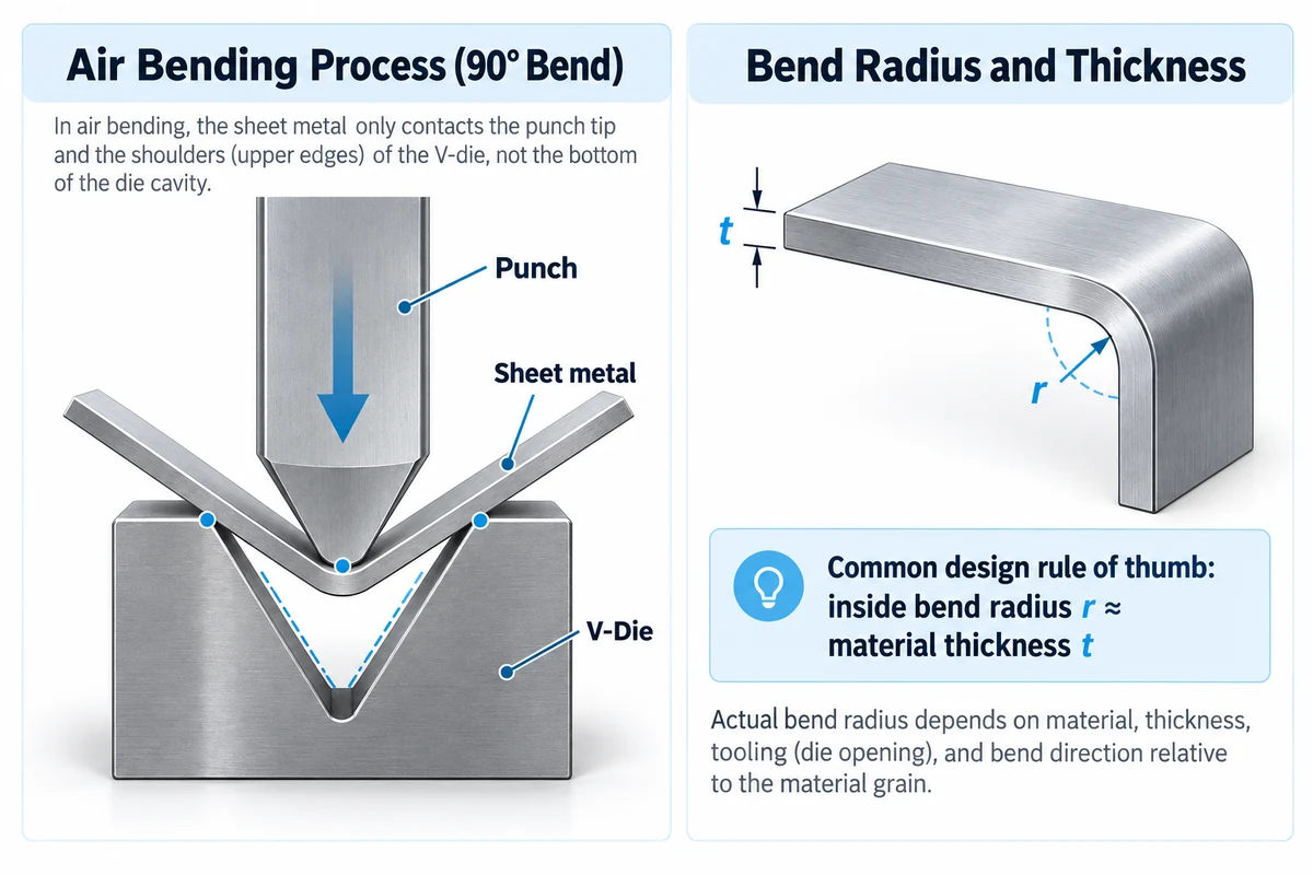
In air bending, the sheet is supported on the shoulders of a V-die while the punch pushes the material into the opening. The sheet does not simply copy the punch nose, so a punch with a 2 mm nose radius does not automatically produce a 2 mm inside radius on the finished part.
Changing the V-die opening changes the bend zone. Material strength, ductility, thickness, and springback also affect the result. Two shops working from the same drawing may use different tooling combinations and process settings, especially if their standard dies and press-brake setups are different.
Different tooling and process settings are common between shops. What matters is whether the finished part meets the specified dimensions, angle, and functional requirements.
For outsourced sheet metal parts, the drawing should therefore focus on the finished condition. If the inside radius is function-critical, give it a realistic allowable range. If flange position and bend angle are what actually control assembly, those dimensions usually deserve more attention than the exact tooling radius used to make the bend.
K-Factor and Flat-Pattern Data Should Not Come Only From CAD Defaults
K-factor describes the location of the neutral axis through the material thickness and is used when calculating bend allowance and flat length. In production, however, it should not be treated like a fixed material property.
The value that works well in practice can shift with material, thickness, bend angle, inside radius, and forming conditions. For that reason, experienced sheet metal shops often build their own bend allowance or bend deduction data instead of relying only on a software default.
If a shop repeatedly bends the same material and thickness with a proven tooling combination, first-piece and production history become useful references for the next job. For repeat work, that validated shop data is often more practical than debating a theoretical K-factor.
The same applies when a customer provides a flat pattern. The supplier should know whether that flat is only a reference or whether it must be used as provided. If the bend allowance behind the customer’s flat does not match the supplier’s actual tooling and process data, using it without review may shift the final flange dimensions.
When Is “Inside Radius = 1T” Good Enough?
Using an inside radius equal to one material thickness is a common early-design rule of thumb. It can be useful for a quick manufacturability check, but it should not be treated as a universal rule.
A 1 mm mild steel sheet, 1 mm 5052 aluminum sheet, 1 mm 6061-T6 sheet, and 1 mm stainless steel sheet do not behave the same way in bending. Material condition, strength, and ductility all affect springback and cracking risk, especially as the requested radius becomes tighter.
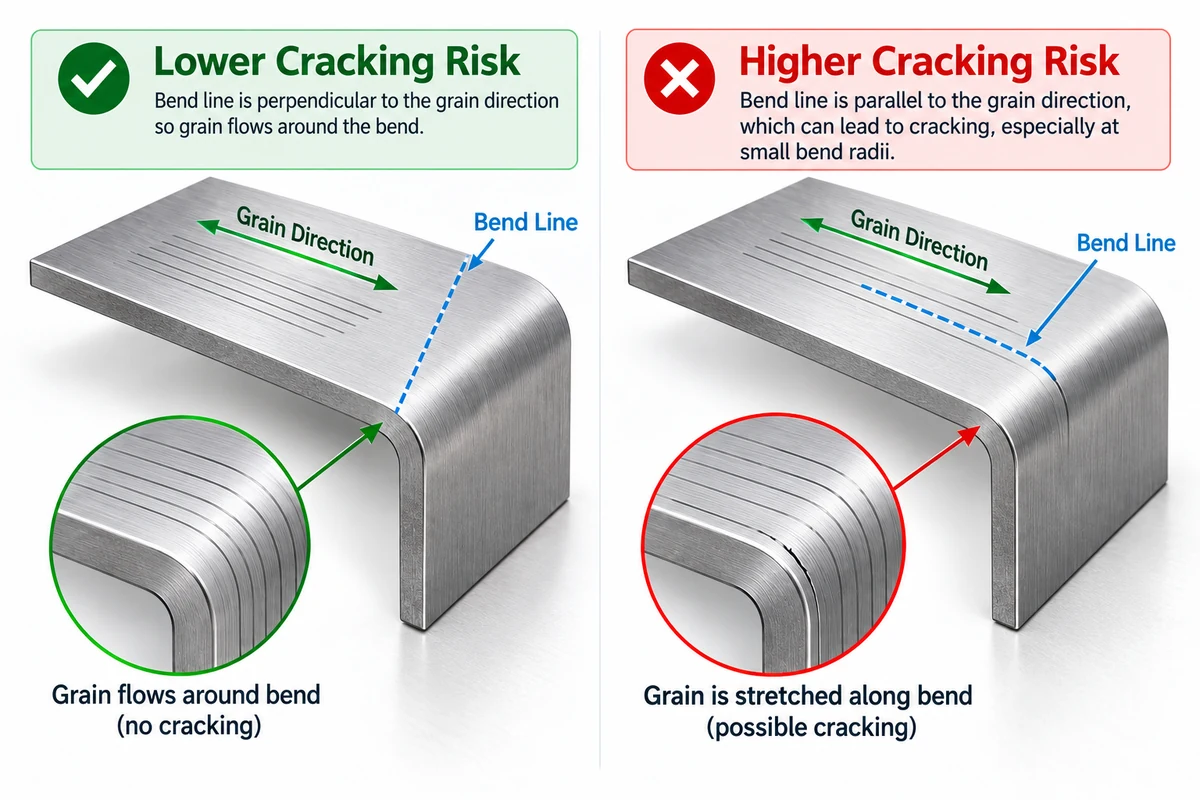
For 6061-T6 and other heat-treated aluminum alloys, rolling direction also matters. The relationship between the bend axis and the rolling direction can affect cracking risk on the outside surface of the bend. This becomes more important with tighter radii, stronger aluminum alloys, and thicker sheet.
In these cases, the better approach is to use material behavior and shop experience for the initial check, then confirm the result with an actual trial bend. Rules such as 1T or 2T are useful for early design screening, but they should not be treated as automatic production limits.
Different Bending Methods Do Not Control Radius in the Same Way
Air bending, bottoming, and coining do not form the material under the same contact conditions.
Air bending is flexible because the sheet is not fully forced into the die cavity. The final angle and inside radius are more sensitive to material, V-die opening, punch penetration, and springback.
Bottoming and coining constrain the material more strongly with the tooling, so the relationship between tool geometry and finished geometry is different.
For most custom sheet metal work, the customer does not need to specify the exact bending method on the drawing. If the finished part meets the required radius, angle, and flange dimensions, the supplier should generally be free to choose the process that works best with its equipment and tooling.
When the radius affects fatigue, sealing, or a special assembly condition, it should be discussed during DFM review. At that point, the conversation should include material condition, tooling, and first-piece verification—not only the nominal R value.
Bend radius also affects more than the curved corner itself. It changes bend tangent location, developed length, and final flange position. Holes and slots close to the bend zone can also move or distort because of local stretching and compression. Bend radius, bend allowance, flange dimensions, and hole-to-bend distance are therefore related design variables, even though hole-to-bend distance is better treated as its own DFM topic.
How Should Bend Radius Be Shown on the Drawing?
Not every bend needs the same level of control. The drawing should reflect how much the radius actually matters to the part.
| Design Condition | Better Drawing Practice |
| Radius affects assembly, interference, or another function | Specify the finished inside-radius range, or a maximum/minimum value |
| Radius has little functional impact | Avoid unnecessarily tight radius tolerances and allow standard shop tooling |
| Flange end position is more important | Control the finished flange dimension and bend angle |
| Customer supplies a flat pattern | State whether the flat is reference-only or mandatory, and have the supplier confirm it |
| High-strength material, tight radius, or thicker sheet | Review material condition, rolling direction, and trial-bend results |
| Multiple materials or thicknesses are used | Do not assume the same K-factor or bend deduction applies to all of them |
For repeat production, the first article or first-piece result is especially useful. If a flange shows a consistent offset after bending, the flat-pattern data can be corrected and the validated result can be saved for future runs. The next batch then starts from proven information rather than from a generic default.
This accumulated shop experience is one reason bend data can differ from one manufacturer to another, even when similar CAD systems and press brakes are used. The useful data is the data that has been validated on the shop’s own machines, tooling, and materials.
Conclusion
Sheet metal bend radius should not be treated as a single CAD value isolated from the forming process. In air bending, the final radius is affected by material, thickness, V-die opening, springback, and tooling. Materials that are more difficult to form may also require attention to temper and rolling direction.
A good drawing makes the functional requirements clear: which radii matter, which angles matter, and which finished dimensions control assembly. V-die selection, tooling combinations, bend deduction, and other process parameters are usually better left to the supplier’s proven manufacturing process.
Rules of thumb such as “R = 1T” and generic K-factor values are useful starting points. For production work, however, validated trial-bend and first-piece data are usually more reliable than a universal theoretical number.
Ready to Review Your Sheet Metal Design?
Share your drawing, 3D model, material, thickness, and key bend requirements. Our team can review bend radii, forming conditions, critical dimensions, and other DFM details before quotation or production.REQUEST A QUOTE
References & Sources
Autodesk — How to Calculate K-Factor for Inventor Sheet Metal
Technical reference for K-factor, bend allowance, and using measured bent parts to refine flat-pattern calculations.
The Aluminum Association — Designing Aluminum Structures FAQs
Reference for how alloy, temper, thickness, grain orientation, and bend angle affect minimum bend radius in aluminum.
Bystronic — The Rules of Press Brake Tool Selection
Technical reference for V-die selection and the relationship between V-die opening and inside radius in air bending.
FAQ
Is the inside bend radius always the same as the punch radius?
Not necessarily. In air bending, the final inside radius is also influenced by the V-die opening, material thickness, material condition, bend angle, and springback.
Is K-factor fixed for each sheet metal material?
It varies with the forming conditions. K-factor is used for flat-pattern calculations, but the practical value can change with material, thickness, radius, bend angle, and the bending process. For repeat production, validated bend allowance or bend deduction data is usually more useful than a generic default.
Should every bend radius be tightly specified on a sheet metal drawing?
Only when the radius affects the part’s function. This may include assembly clearance, sealing, fatigue, appearance, or interference with another component. If the radius has little functional impact, an overly tight callout can restrict tooling without improving the part.
Can a supplier use my flat pattern directly?
In some cases. The supplier should first confirm that the bend allowance or bend deduction used in the flat pattern matches the actual tooling and forming conditions. Otherwise, the flat may need to be adjusted or regenerated.