Article Summary
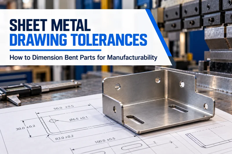
Learn how to properly dimension and tolerance bent sheet metal parts, the difference between functional datums and chain dimensioning, flat pattern vs formed dimensions, and how to allocate tolerances with GD&T best practices for manufacturability.
One of the most common causes of sheet metal drawing disputes isn’t poor fabrication — it’s unbalanced tolerances and unclear functional datums. In our press brake shop, this is a frequent source of drawing conflicts: a flat laser-cut part passes all dimensional checks, yet fails to fit after bending. The problem rarely originates at the cutting stage. Our laser cutting services deliver tight flat-profile accuracy, but bending introduces additional variables: material springback, inside bend radius, press brake condition, tooling wear, and bend sequence all shift final feature positions.
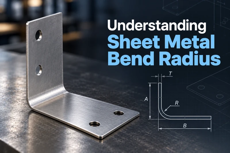
For more on how springback and inside radius affect forming results, see our sheet metal bend radius design guide. For bent parts, dimensional control cannot be judged by individual flat dimensions alone — it must be evaluated around final assembly requirements.
Not Every Dimension Deserves the Same Tight Tolerance
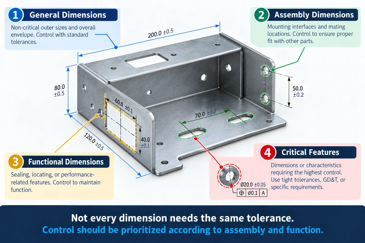
Not every dimension deserves the same tight tolerance. A sheet metal enclosure may have dozens of mounting holes, but only a small set of locating holes define the true assembly position. Applying the same positional control to every hole drives up manufacturing and inspection cost with no functional gain. For parts like small equipment enclosures and mounting brackets, typically only the locating holes require tight control, while outer profiles and ventilation holes can follow standard tolerances.
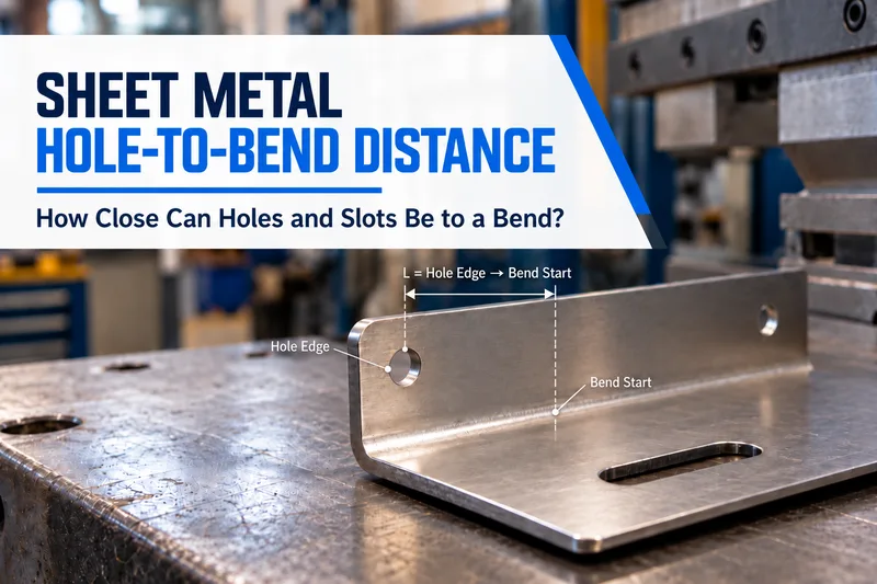
For detailed guidance on hole positioning and distortion risk near bends, refer to our hole-to-bend distance design guide. Good engineering drawings prioritize dimensions that directly affect function: locating holes, sealing faces, mounting interfaces, and critical fit areas, rather than applying uniform precision across every feature on the part.
Functional Datums Beat Chain Dimensioning
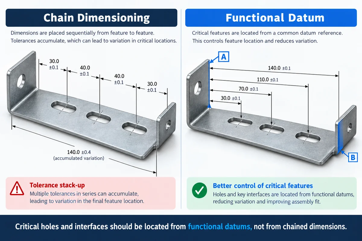
Dimensioning sequentially from the part edge creates stacked error. Each dimension carries its own tolerance, and when multiple dimensions are chained end-to-end, total deviation at the final feature can exceed assembly limits. For sheet metal parts that must hold assembly relationships, a functional datum system is far more reliable.
For example, if you chain three consecutive ±0.1 mm dimensions from the part edge to a locating hole, total positional error can stack up to ±0.3 mm. Using a single functional datum directly to the hole cuts that variation roughly in half. ASME Y14.5, a widely used dimensioning and tolerancing standard, defines this as the Datum Reference Frame, a standard framework for expressing geometric relationships between features and communicating design intent to fabricators.
Flat Pattern vs. Formed Part Dimensions
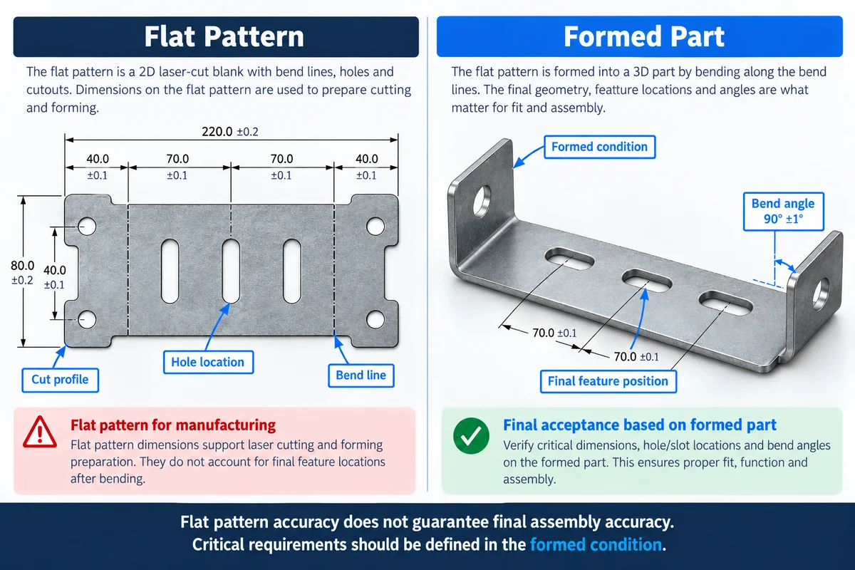
Flat pattern drawings exist for laser cutting and manufacturing preparation, but the end product functions in its bent, three-dimensional state. This means a correct flat pattern does not guarantee correct assembly dimensions. For critical mounting features, acceptance criteria must be specified for the formed condition, not just the flat blank.
This is a classic point of misalignment between design offices and fabrication vendors. Dimensional variation during the bending and forming process is driven by material, tooling, and process factors, and cannot be measured by flat-part accuracy alone.
How to Allocate General vs. Critical Tolerances
Tolerance planning isn’t about tightening every dimension just to be safe. It is about tightening control where it affects function, and using reasonable general tolerances everywhere else. Non-critical outer profiles can usually follow standard commercial tolerances, while locating holes, sealing faces, and assembly interfaces require individually defined limits.
Common Tolerance Reference Ranges
(Applicability: 1.0–2.0 mm cold rolled steel, standard V-die bending; baseline industry reference only, not a guaranteed accuracy for all materials and processes)
- General outer dimensions: ±0.2 mm per 100 mm, or ±0.3–0.5 mm for non-critical features
- Standard mounting holes: ±0.1 mm
- Precision locating holes: ±0.05 mm
- Bend angles: ±0.5° to ±1°
Actual values vary by material, thickness, tooling, and production method.
GD&T for Sheet Metal Parts
When part function depends on the relative position of multiple holes, the orientation of a mounting face, or reference to a common datum, Geometric Dimensioning and Tolerancing (GD&T) usually communicates design intent better than stacked linear dimensions. For bent sheet metal parts, the two most widely used GD&T callouts are Position and Flatness.
Position is used for hole patterns and locating features, referenced to a functional datum. Flatness applies to mounting faces, sealing surfaces, and features that require consistent contact. Locating hole arrays, equipment mounting surfaces, and gasket sealing zones are all better defined from a functional datum framework than with separate ± tolerances.
Why Tighter Tolerances Drive Up Manufacturing Costs
Tighter tolerances require more stable processes, more frequent inspection, and additional first-article validation, but not every dimension is worth that extra cost. We routinely see drawings where every tolerance is tightened “just to be safe,” which can notably increase part cost with zero functional benefit.
The correct approach is to match tolerance strictness to what the part actually needs to do, rather than tightening every dimension indiscriminately.
What a Production-Ready Sheet Metal Drawing Includes
A complete, fabricator-friendly drawing defines the end result without restricting the production method. At minimum, it should cover six core elements: material, bend requirements, datums, critical dimensions, surface finish, and inspection criteria.
| Drawing element | Specification |
|---|---|
| Material | Grade, thickness, temper |
| Bend requirements | Bend angle, inside radius, special notes |
| Datums | Functional reference and inspection basis |
| Critical dimensions | Features that affect assembly and fit |
| Surface finish | Coating, masking, cosmetic requirements |
| Inspection requirements | Acceptance criteria for key features |
Dimension Type Breakdown
| Dimension Type | Examples | Control Approach |
|---|---|---|
| General dimensions | Non-functional outer profiles, standard edges | General commercial tolerances |
| Assembly dimensions | Interfaces, gaps, mounting locations | Defined by assembly requirements |
| Functional dimensions | Locating holes, sealing faces, fit areas | Individually controlled with explicit inspection |
| Critical quality features | Performance-critical dimensions | Defined with dedicated inspection criteria |
Conclusion
No single universal tolerance rule works for every bent sheet metal part. General tolerances, critical dimension control, functional datums, and GD&T all have their place. The goal is to match tolerance strictness to actual functional need, not to make every dimension as tight as possible.
Chain dimensioning works for simple parts, but functional datums reduce error stackup on assemblies with critical fit requirements. Flat pattern dimensions are useful for production, but formed-part dimensions define whether the part actually works. Backed by 20+ years of press brake production experience, our engineering team reviews a high volume of sheet metal drawings every month for DFM feasibility.
If your sheet metal drawings have a history of dimensional disputes, low fabrication acceptance rates, or assembly fit issues, you can send your 3D models and drawings to us for a DFM manufacturability review. Our team will identify dimensioning issues and recommend practical, cost-aligned tolerance adjustments from a production perspective.
References & Sources
- ASME Y14.5 — Dimensioning and Tolerancing Standard; Datum Reference Frame definition
- ISO 8015 — Geometrical Product Specifications (GPS) Fundamentals — Official ISO standard for GPS fundamentals, concepts and dimensioning rules
- Protolabs Sheet Metal Design Guidelines — Industry fabrication reference only, not a mandatory standard
- Xometry Manufacturing Standards — Industry fabrication reference only, not a mandatory standard
FAQ
Do flat pattern dimensions match final bent part dimensions?
Not always. Flat pattern dimensions are for manufacturing preparation; final assembly and acceptance are based on the formed part condition.
Why do different suppliers produce different results from the same drawing?
Material variation, press brake tooling, die condition, process sequence, and inspection method all affect final dimensional results.
Does every dimension on a sheet metal drawing need a separate tolerance?
No. Focus tolerance control on dimensions that affect assembly, location, and performance.
When should GD&T be used instead of standard ± tolerances?
GD&T is preferred when function depends on the position, orientation, or datum relationship between features.