Article Summary: Learn how to evaluate sheet metal hole-to-bend distance, why holes and slots distort near bends, how common rules such as 2T + R and 4T should be interpreted, and what to do when a critical feature cannot be moved.
A hole can be perfectly round in the flat pattern and still come out distorted after bending. The cut may be accurate, the hole location may check correctly before forming, and yet the finished part shows an oval hole, a stretched slot, or a feature that no longer sits where the assembly expects it to be.
The usual explanation is that the hole was “too close to the bend.” That is directionally correct, but it does not tell a designer what to do next. Rules such as 2T + R, 2.5T + R, and 4T appear throughout sheet metal design literature, but they do not all use the same reference points or assume the same tooling and forming conditions.
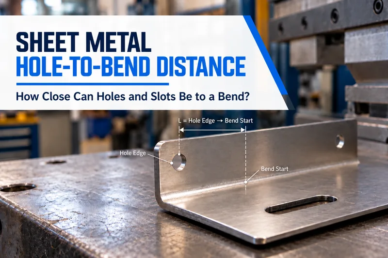
Before applying any rule, it helps to answer a simpler question: Where, exactly, is the hole-to-bend distance being measured from?
Define the Bend Reference Before Applying a Distance Rule
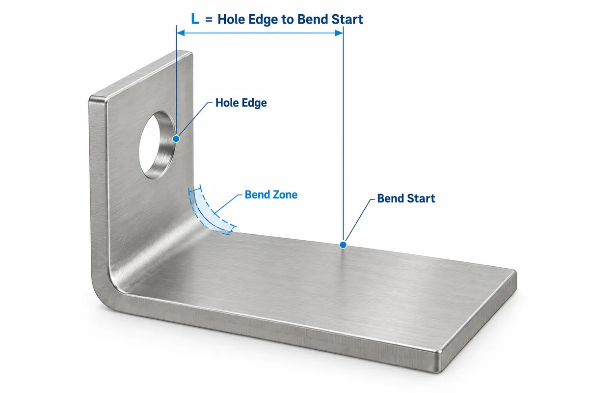
A bend is not a zero-width line.
In CAD and sheet metal documentation, the bend can be referenced by its start, centerline, or end. Autodesk Inventor, for example, distinguishes between Start of Bend, Centerline of Bend, and End of Bend when locating a sheet metal fold. This reflects the fact that the material actually deforms across a bend zone rather than along a single mathematical line.
That distinction matters when a drawing says something like “Keep the hole at least 4T from the bend.” Two questions are still unanswered: Is the distance measured from the hole center or from the nearest edge of the hole? Is the other reference the bend centerline, the start of bend, or another bend-zone boundary?
For features that sit close to the forming zone, those definitions can change the actual CAD location by a meaningful amount.
| Drawing reference | What it represents | Why it matters |
|---|---|---|
| Hole center | Geometric center of the hole | May not be the first part of the feature to enter the bend zone |
| Nearest feature edge | Hole or slot edge closest to the bend | Often more useful when evaluating local distortion risk |
| Bend centerline | Center reference of the bend | Should not automatically be treated as the start of deformation |
| Bend start / tangent area | Where the flat sheet begins transitioning into the bend | Commonly relevant when evaluating clearance from the forming zone |
| Bend end | Opposite boundary of the bend region | Helps define the full bend zone |
Hole-to-bend distance is related to bend radius, but the two are not interchangeable. The inside radius affects the geometry of the forming zone; hole-to-bend distance deals with what happens when a nearby feature begins to interact with that zone.
For a deeper discussion of radius, material thickness, and forming conditions, see our Sheet Metal Bend Radius Guide.
Why a Hole Can Distort Even When the Flat Pattern Is Correct
At the cutting stage, the part is still flat. The deformation begins during forming.
As the sheet bends, material on the outside of the bend is stretched while material on the inside is compressed. If part of a hole or slot falls within the active forming region, the material around that feature is pulled into the same plastic deformation.
A round hole may become slightly oval. One side may elongate more than the other. A slot may stretch at the end nearest the bend. In some cases the feature still looks acceptable by eye, but its final position relative to another mounting point has changed.
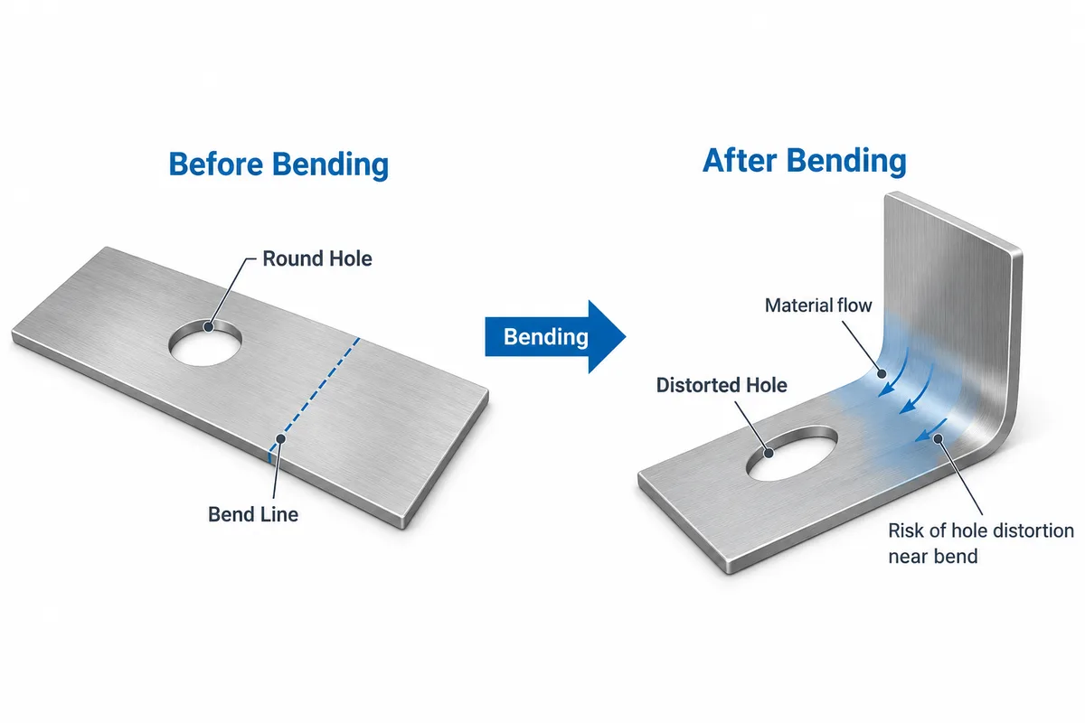
This is why improving laser-cutting accuracy alone does not solve the problem. Cutting controls the flat geometry; the distortion develops later in the forming operation.
A 2022 experimental study on V-die bending of sheets containing holes found that hole location and hole diameter affected bending behavior and springback. Features located in or near the bend-radius region interacted more strongly with the forming process than holes positioned farther away in the leg region.
For parts where flat-pattern accuracy is itself a concern, our sheet metal laser cutting capabilities cover the cutting stage before the part moves into forming.
Why Do Some Guidelines Use 2T + R While Others Use 4T?
Because they are not always describing exactly the same conditions.
A 2025 study focused on minimum hole position in L-die bending used dmin = 2t + r for holes below 25 mm in diameter and dmin = 2.5t + r for holes 25 mm and larger. The purpose was to identify a minimum distance that reduced hole distortion under the specific forming conditions studied.
In these equations, T is sheet thickness and R is inside bend radius. Use the same unit for both values.
U.S. example: A 14-gauge 304 stainless steel sheet is approximately 0.078 in. (1.98 mm) thick. If the inside bend radius is 0.090 in., a 2T + R screening value is approximately 0.246 in. (6.25 mm). This is a design reference only; the final required clearance still depends on how the distance is defined and on the actual forming process and tooling.
Older sheet metal design handbooks also use the 2T + R and 2.5T + R approach under “forming near holes,” particularly when distinguishing between smaller holes and larger holes or slots.
Other fabrication guidelines take a more conservative screening approach. A current sheet metal fabrication design guideline flags features located within roughly four material thicknesses of a bend as being at increased risk of deformation.
These values are useful, but they should not be treated as three competing international standards.
| Common approach | Best use | What to avoid |
|---|---|---|
| 2T + R | Early design reference for relatively small holes | Applying it universally without checking the original measurement definition |
| 2.5T + R | Reference for larger holes or some slot conditions | Ignoring slot orientation or actual tooling |
| 4T | Conservative screening for features near the forming zone | Treating it as an ISO/ASME acceptance requirement |
| Supplier/tooling-based DFM | Final manufacturing review | Using it without actual material, radius, V-die, and machine conditions |
At the concept stage, these rules are useful for identifying areas that deserve attention. Before production, the actual material, thickness, inside radius, press-brake tooling, and feature function matter more than the shorthand formula alone.
Our bending and forming capabilities cover different materials, thicknesses, and V-bending conditions, so features near the process limit are reviewed against the actual part rather than a single universal multiplier.
A Vent Hole and a Locating Hole Should Not Be Treated the Same Way
Two holes can have exactly the same distance from a bend and still require different design decisions.
A ventilation or weight-reduction hole may tolerate slight ovality without affecting the product. A standard clearance hole may also have enough assembly allowance that minor forming movement does not matter.
A locating hole, bushing bore, bearing feature, or other mating feature is different. Its size and position may directly control assembly. A small amount of distortion that is harmless for a vent hole can make a locating feature unusable.
Slots require another level of attention. Measuring only from the slot center can hide the real risk. The slot center may appear safely away from the bend while the end radius closest to the bend has already entered the forming zone.
| Feature type | Main concern | Typical response |
|---|---|---|
| Ventilation / lightening hole | Minor ovality or cosmetic change | Accept deformation if function allows |
| Bolt clearance hole | Remaining assembly clearance | Verify final hole shape and usable clearance |
| Locating / mating hole | Position, roundness, fit | Increase distance or finish-machine after bending |
| Long slot | Slot end entering the bend zone | Evaluate the full slot profile, not only its center |
| PEM mounting hole | Out-of-round hole, loss of flatness, tooling clearance | Check the specific fastener requirements separately |
For features that cannot be judged reliably from a general design rule, the hole location, bend direction, radius, material, and assembly requirements can be reviewed together during DFM engineering review.
PEM Mounting Holes Need an Additional Check
Self-clinching fastener holes should not be treated as ordinary clearance holes.
PennEngineering's technical guidance for fasteners located near bends requires more than a general hole-to-bend rule. The mounting area needs to remain flat, the fastener must clear the bend radius, the applicable minimum centerline-to-edge distance must be respected, and installation tooling still needs enough access.
PennEngineering also identifies another practical problem: if a mounting hole is punched before a nearby bend is formed, the bend can pull that hole out of round. For these conditions, the recommended sequence is to form the bend first and produce the mounting hole afterward.
That means a PEM hole can satisfy a general hole-to-bend guideline and still fail the actual fastener installation requirements. The specific fastener series, mounting-hole size, centerline-to-edge requirement, flat area, and tooling access all need to be checked.
What If the Hole Cannot Be Moved?
In real products, hole locations are often constrained by other components.
A PCB, connector, fastener, enclosure seam, or neighboring assembly may already define the position. This is especially common in compact enclosures, panels, and mounting brackets.
When moving the hole is not practical, the manufacturing route can sometimes solve the problem.
| Situation | Possible approach | Trade-off |
|---|---|---|
| Minor distortion is acceptable | Keep the current design | Lowest cost; verify on the first article |
| Critical hole must hold size or position | Drill, ream, or CNC-machine after bending | Additional setup and machining time |
| Long slot enters the bend zone | Adjust position, orientation, or local profile | Assembly may need to be rechecked |
| Local material is heavily constrained | Add bend relief or a cutout | Local stiffness and section geometry change |
| PEM hole is close to the bend | Change piercing, bending, and installation sequence | Must still meet fastener installation requirements |
| Design space is already fixed | Validate using the actual production tooling | More up-front validation, lower production risk |
If a locating hole becomes unusable after bending, saving one secondary operation does not help the project. At the same time, a slightly oval ventilation hole may not justify any extra machining at all.
That is where DFM becomes more useful than a fixed clearance table: the manufacturing decision can follow the function of the feature.
Conclusion
There is no single sheet metal hole-to-bend distance that works for every part.
Rules such as 2T + R, 2.5T + R, 4T, and tooling-based clearance guidelines are useful for early design screening. Before production, however, the designer and manufacturer still need to confirm how the distance is measured, what material and tooling will be used, and what the feature must do after forming.
A small amount of distortion that is acceptable for a ventilation hole may be unacceptable for a locating hole or PEM mounting feature. When a critical feature cannot be moved, post-bend machining, local relief, or a revised process sequence may be more practical than forcing the design to comply with a single generic multiplier.
If a hole, slot, or hardware mounting feature in your design sits close to a bend, you can send the 3D model and drawing for a manufacturability review before production.
References & Sources
• Autodesk Inventor — Sheet Metal Bend/Fold Documentation — Supports the distinction between bend start, bend centerline, bend end, and the bend region.
• Thipprakmas & Sontamino — Spring-Back Characteristics on Bent Holed Parts in V-Die Bending Process (2022) — Experimental evidence for the effects of hole location and hole diameter on forming behavior and springback.
• PennEngineering — Self-Clinching Fastener Technical Guidance — Supports bend proximity, mounting-hole sequence, flat installation area, edge distance, and tooling clearance requirements.
• Sheet Metal Fabrication Design Guidelines — Used only as context for the conservative 4T feature-proximity screening rule, not as an international acceptance standard.
FAQ
Can a larger V-die reduce hole distortion near a bend?
It can change the result, but a larger V-die opening is not automatically better. Changing the die opening also changes sheet support, the active forming zone, and the resulting inside radius, so the relationship between the hole and the bend zone changes as well. If the feature is already near the process limit, material, thickness, target radius, and actual tooling should be evaluated together.
Can I make a smaller pilot hole first and enlarge it after bending?
Yes. If the final hole has tight requirements for size, roundness, or location, a smaller pilot hole can be produced in the flat part and then drilled, reamed, or machined to final size after bending. This reduces the dependence of the finished feature on the forming operation, although it adds another setup and is usually reserved for function-critical holes.
Can bend relief or a local cutout reduce distortion around a nearby hole?
Yes, but the structural effect also needs to be reviewed. A properly designed bend relief or cutout can change how material flows through the bend and reduce interaction with a nearby feature when space is limited. At the same time, the relief changes the local section and stiffness, so load-bearing areas should be evaluated against the actual structural and assembly requirements.
Should a PEM mounting hole near a bend be punched before or after bending?
For self-clinching fastener mounting holes located close to a bend, PennEngineering recommends forming the bend first and producing the mounting hole afterward to reduce the risk of pulling the hole out of round. The installation area must also remain flat, the fastener must clear the bend radius, and enough space must remain for installation tooling.