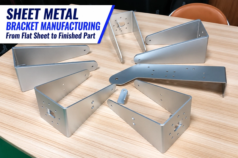
The sheet metal bracket manufacturing process usually starts with cutting a flat blank. Bending, die forming or welding then creates the required structure, followed by any specified fastener installation, finishing and inspection. The route depends on the bracket geometry, mounting requirements, order quantity and subsequent operations.
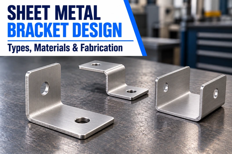
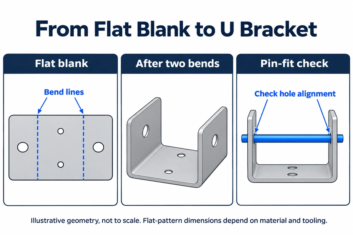
This guide follows an illustrative U-shaped mounting bracket: its base attaches to equipment, and a pin passes through holes in the two sidewalls. It is formed from one sheet with two bends and does not represent an actual customer project. Welded construction is discussed as a separate manufacturing route.
Manufacturing Routes for Sheet Metal Brackets
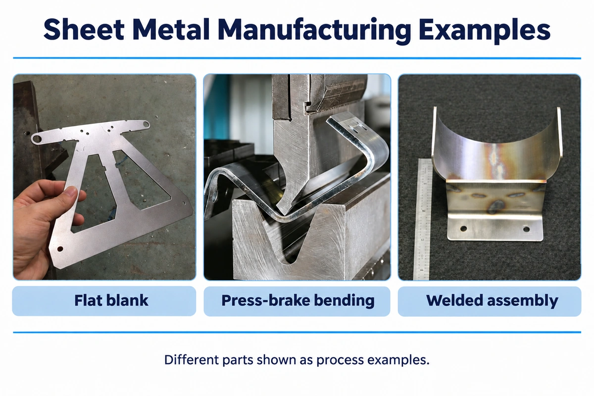
For a cut-and-bend route, production starts by confirming the finished-part drawing, material and thickness. The fabricator develops the flat pattern, cuts or punches the blank outline and holes, finishes the specified edges, and bends the part. Required hardware installation and surface finishing are included in the process plan, followed by finished-part inspection and a trial assembly.
A blank is the flat part before bending. Flat-pattern dimensions depend on the material, thickness, bend radius and actual tooling. Once both bends are complete, acceptance focuses on how the base mounts, the spacing between the sidewalls and the relative positions of the pin holes.
| Manufacturing route | When to consider it | Main factors to review |
|---|---|---|
| Cutting or punching followed by bending | One-piece brackets and designs that may change | Tool access, bend sequence, hole positions and bend radius |
| Die stamping | Stable designs with repeat orders | Tooling investment, die stations, material formability and revisions |
| Cutting and forming separate parts, then welding | Joining separate components or adding reinforcement | Joint design, workholding access, distortion and inspection after welding |
Laser cutting follows a digital contour. CNC punching uses a punch and die to produce holes and profile features. The choice depends on geometry, sheet thickness and available tooling.
Stamping uses a press and dies to cut or form sheet. Operations may be performed separately or combined in a multi-station die. In a progressive die, the strip carries the work through successive stations before the finished part is separated. SME's sheet metal stamping guide describes these approaches.
For repeat orders, provide the release quantity, delivery frequency and expected design changes when comparing metal stamping with cutting and bending. Small batches may use existing stamping tools, while larger orders may still use cutting and bending. A single quantity threshold cannot determine the route.
Welded construction can connect separate mounting plates, parts of different thicknesses or structures that cannot be made as one piece with the available bending tools. Where reinforcement is needed, added flanges or a revised flat pattern may reduce the number of separate parts. TRUMPF's part optimization guide includes a welded bracket redesigned as a single bent part, but any proposed change still needs checks for loads, deflection and assembly space. The three routes can be combined; none has a fixed overall ranking.
Process Details That Affect the Finished Bracket
Develop the Flat Pattern and Bend Sequence Around the Finished Part
After one side of the U bracket is bent, it may obstruct the tooling for the second bend. Review bending and forming alongside the flat pattern so the part can be located, the tools can reach it, and any later hole machining or self-clinching operation remains accessible.
Material springs back when the bending load is removed. SSAB's springback guidance explains this behavior in steel. Set compensation and machine adjustments for the material and actual forming conditions. Inspect the unloaded bend angles, distances between mounting surfaces and critical hole positions rather than applying a fixed correction from another grade.
Coordinate Holes and Fasteners with Later Operations
Ordinary clearance holes can be made in the flat blank. Holes close to a bend, locating holes on different bent faces, and holes that must retain their relative positions after welding need a review of how later operations affect their shape and location.
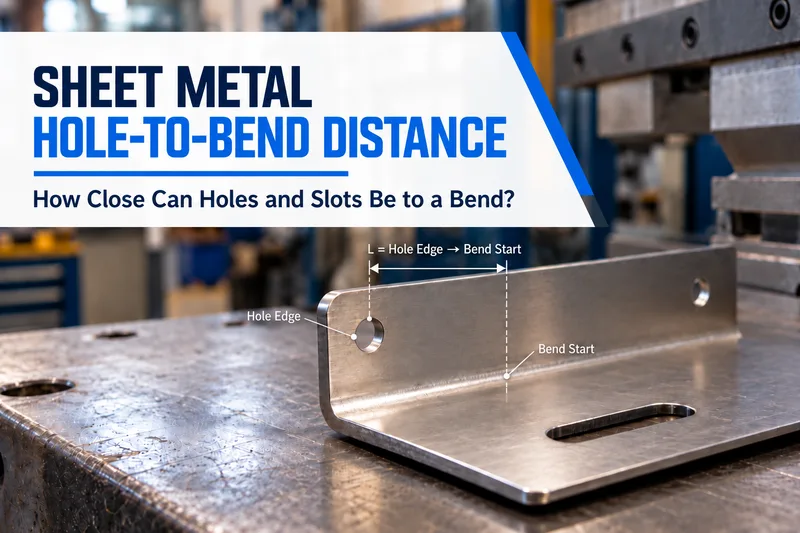
The pin in this U bracket must pass through both sidewalls. Checking hole spacing in the flat pattern is therefore insufficient: the holes must align and provide the required pin fit after bending. Options include changing the hole layout or forming method, or using post-bend drilling or reaming. Confirm workholding and tool access, and avoid distorting thin sheet during clamping. Our hole-to-bend distance guide discusses holes near bends.
For self-clinching nuts, specify the part number and installation direction, then confirm the permitted sheet thickness and hardness. A note stating only “M4 thread” does not distinguish a directly tapped hole, an extruded and tapped hole, or an installed nut.
Prepare the mounting hole to the requirements for the selected fastener. PennEngineering's installation guidance warns that deburring a mounting hole before installation can remove material needed for clinching. Requirements for ordinary cut edges should therefore be kept separate from self-clinching holes; do not add a blanket chamfer to every hole.
During installation, keep the punch and anvil faces parallel. Confirm installation force, the minimum distance from the hole center to the sheet edge, and sheet conditions for the selected part number. Whether nuts are installed before or after bending also depends on tool access and the effect of bending on the mounting holes.
The PEM Self-Clinching Fastener Handbook requires installation before painting or powder coating for the fasteners covered by that guidance. Plan the sequence accordingly and protect threads and relevant mating areas. For plating or anodizing, confirm the sequence separately for the fastener part number, panel material and finishing requirements.
Account for Welding and Finishing in the Assembly
For welded assemblies, control joint design, sequence and workholding, then inspect mounting surfaces, hole positions and joints after cooling. TWI's distortion guidance identifies the welding process, weld design and sequence as control factors. Distinguish measurements taken while the part is restrained from those taken after it is released. Specify the extent of visible weld grinding to avoid damaging the parent material or changing the joint requirements. Discuss the required scope through our welding and assembly capabilities.
Powder coating, plating or anodizing must suit the material and environment, and may change dimensions at mating features. Specify whether holes, threads, mating surfaces and electrical contact areas are to be treated or masked according to their function. With powder coating, protect nut threads as agreed and check fastening access and mating clearances after finishing.
Inspecting the Finished Sheet Metal Bracket
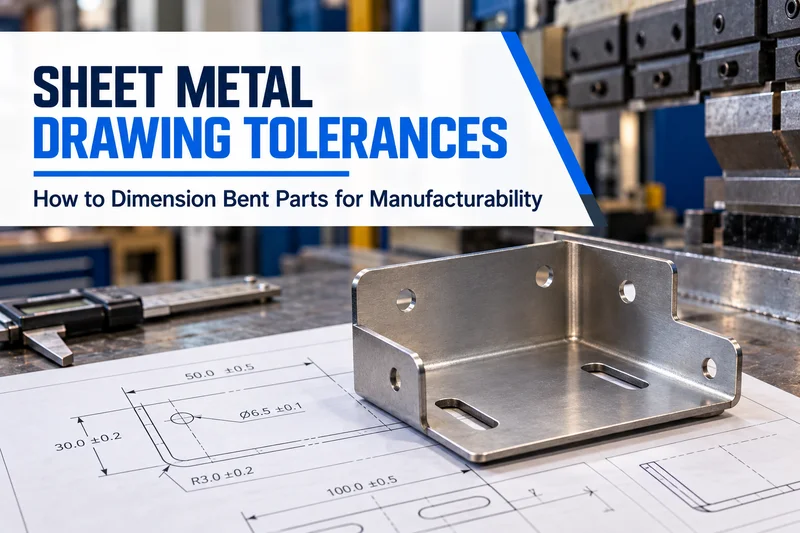
Relate critical dimensions to the actual mounting datums and state whether acceptance applies after forming, welding or finishing. Also define whether measurements are taken in the free state, in a specified fixture or in the assembled condition. See our sheet metal drawing tolerances guide for dimensioning considerations.
Mounting the U bracket on the equipment and inserting the pin checks base contact, side-hole alignment and fastening access together. If bolts must force the bracket into contact, review the angles, dimensions and specified assembly method. Distinguish permitted assembly deflection from manufacturing error.
| Inspection stage | Main features to check |
|---|---|
| After forming | Bend angles, opening width, mounting height and critical hole positions |
| After welding | Mounting surfaces, relative component positions and joints after cooling |
| After finishing | Mating holes, threads, contact surfaces, masked areas and appearance |
| Trial assembly | Mating parts, tightening, removal and tool access |
Samples should represent the planned delivery condition, including specified hardware and finishing, and should be trial-assembled with the actual mating parts. Retain the approved sample, drawing revision and main manufacturing requirements. If production changes the process or finishing sequence, reconfirm the affected features.
Dimensional inspection and load validation are separate tasks. If load capacity, deflection or fatigue performance must be verified, define the loads, mounting arrangement and acceptance conditions separately. A dimensional report alone does not establish that load validation has been completed.
Information to Prepare for a Custom Bracket Quote
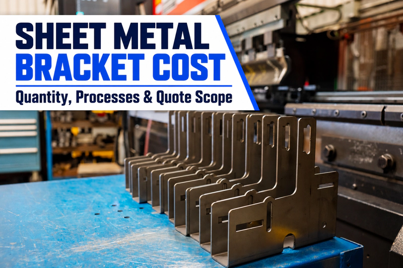
Submit the finished-part drawing or 3D model with the material grade, condition or temper, and thickness. Include release quantities, expected repeat orders, critical mounting dimensions, hardware, finishing and acceptance requirements. Ask the supplier to explain the manufacturing route, any additional machining and the scope of delivery. Our bracket cost and quotation guide explains how to compare costs.
For custom mounting components, explore Tongyong's sheet metal brackets and mounting components, then use our contact page to share a drawing, sketch or model with the mounting application and delivery requirements to discuss a sample plan.
Information Sources
SME — Sheet Metal Stamping Dies & Processes
TRUMPF — Part Optimization
SSAB — Springback
PennEngineering — Self-Clinching Nut Fastener Installation Do’s and Don’ts; Self-Clinching Fastener Handbook
TWI — Distortion Control
FAQ
Do Small Batches of Sheet Metal Brackets Require Dedicated Stamping Dies?
Not necessarily. Compare existing tools, cutting and bending, and any dedicated tooling that is actually needed. Provide the first-order quantity and possible design changes so the supplier can explain the tooling and preparation required.
Can a Bracket with a Gusset Be Redesigned as a Single Bent Part?
Some designs can, but loads, deflection, tooling and mounting space must be reassessed. Connections between different thicknesses or structures that are difficult to bend may still need separate parts; the engineer responsible for the component should approve the change.
Should Brackets Be Made from Carbon Steel, Stainless Steel or Aluminum?
Select for loads, permitted deflection, weight and environment, then confirm processing requirements. Consider corrosion protection for carbon steel, the appropriate stainless steel grade, and an aluminum alloy and temper suitable for the required bends.
Can You Request a Quote with a Finished-Part Model but No Flat Pattern?
Submit the model with material, thickness, quantity and critical requirements, and ask whether flat-pattern development and process review are included. If a flat pattern already exists, identify who confirms it; finished dimensions, drawing revision and acceptance requirements still need agreement before production.