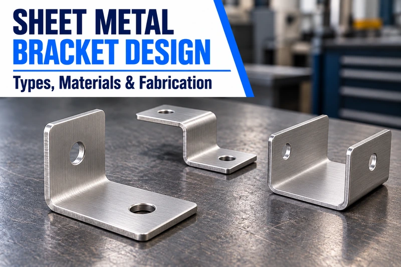
Sheet metal bracket design starts with the mounting arrangement and operating conditions. Establish which parts the bracket will connect or support, the loads it must carry, and the features that must align after assembly. Then select the geometry, material and manufacturing method. L, U and Z describe shapes; brackets with similar outlines can have different thicknesses and connections, so their load capacity and suitability can differ.
In equipment, enclosures and frames, a bracket may need to maintain spacing, allow adjustment, or hold a component in position through vibration and repeated servicing. These requirements help determine whether a design is suitable.
This guide is for engineers and buyers designing, selecting or sourcing custom sheet metal brackets. It explains how mounting and load requirements affect bracket types, materials, thickness, holes, connections and manufacturing options. If you already have a preliminary design, use the finished-sample checklist near the end to review assembly and acceptance requirements.
Define the Operating Conditions Before Designing the Bracket
Start with the relationship between the main mounting surfaces. They may meet at an angle, run parallel at different heights, or sit in the same plane. Some parts need support from both sides. The mounting arrangement determines the basic shape, the bracket's reach and the fastening positions.
Next, establish the loads and allowable deflection. Consider the supported weight, where forces act, vibration or impact, and how much movement would affect function. A tray support and a sensor mount may carry similar weights but have different limits on movement.
Gather the following information before choosing a design:
- Mounted parts and fastening positions: What connects to the bracket, where the mounting surfaces sit, and whether cables, covers or moving parts need clearance.
- Loads and operating conditions: Weight, force direction, offsets, vibration, impact or repeated movement.
- Space and maintenance access: Available space, access for bolts, nuts and tools, and whether components must be removable later.
- Environment and fit requirements: Indoor or outdoor use, moisture or cleaning conditions, and the holes and surfaces that must align.
Without these conditions, asking how thick the sheet should be or which shape is strongest is rarely enough to establish a design.
Choose a Sheet Metal Bracket Type Around the Mounting Arrangement
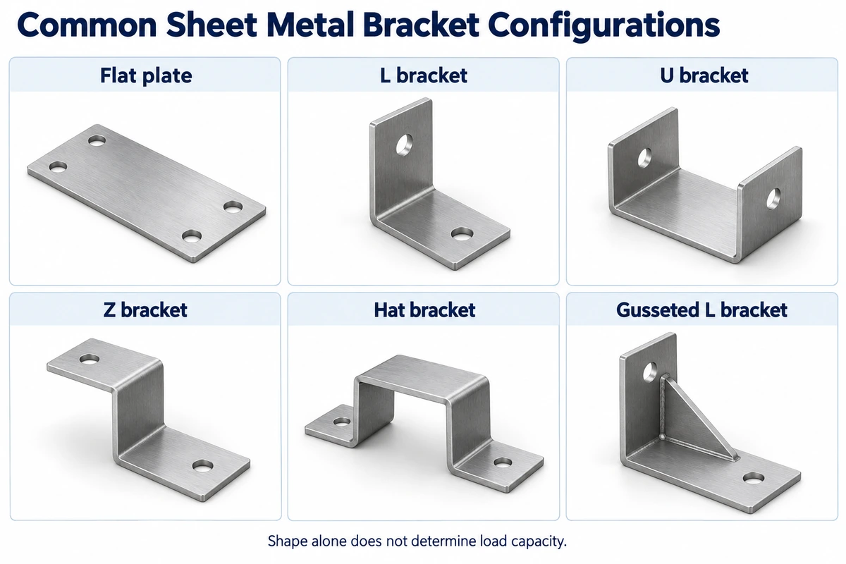
Shape helps identify a bracket, but the way it connects or supports parts matters more. The table identifies common configurations and design checks. It does not rank their load capacity. A custom bracket can also combine these features to suit the layout.
| Type | Typical purpose | Key design checks |
|---|---|---|
| Flat connecting plate | Join, splice or secure parts in the same or nearly the same plane | Fastener positions, overlap, bending and slip at the connection |
| L bracket | Connect mounting surfaces at an angle, often for corner mounting or support | Reach, hole positions, angle and local reinforcement |
| U bracket | Support or contain a part from two sides, such as a component, tube or equipment module | Internal clearance, side height, side-hole positions and tooling access for both bends |
| Z bracket | Connect parallel mounting surfaces at different heights | Offset height, end fastening positions and bending caused by the offset |
| Hat bracket or raised bracket with mounting feet | Raise a mounting surface and leave space beneath it | Height, foot-hole positions, tool access and bend sequence |
| Bracket with reinforcement | Add local support to a basic configuration to reduce unwanted bending or twisting | Reinforcement location, forming or joining method and clearance for tools and adjacent parts |
L brackets are common and simple, but a longer projecting arm can increase deflection. U brackets allow mounting from both sides, although the internal width must accommodate the component and the manufacturing process. Z brackets bridge a height difference, but the offset and reach still need to be assessed against the loads.
Reinforcement can complement L, U or Z shapes. A formed rib and an attached gusset plate require different manufacturing checks; the illustrated L bracket uses an added triangular gusset plate.
Consider Material and Thickness Together
Material affects weight, stiffness, corrosion resistance, formability and finishing. Carbon steel, stainless steel and aluminum can all be suitable, depending on the operating conditions.
| Material | Common reasons for choosing it | Conditions to confirm |
|---|---|---|
| Carbon steel | A practical balance of cost, stiffness and conventional fabrication | Grade, thickness and any paint or plated corrosion protection |
| Stainless steel | Corrosion resistance or cleaning requirements | Actual exposure, grade, forming requirements and surface condition |
| Aluminum | Weight reduction | Alloy and temper, allowable deflection, bendability and finishing |
Strength and stiffness describe different properties. Strength concerns yielding and other failure limits; stiffness concerns how much the bracket deforms under load. Higher-strength steel does not automatically make the same geometry and thickness less flexible. SSAB's structural stiffness guidance distinguishes the roles of material strength, elastic modulus and cross-sectional geometry.
Aluminum can reduce weight, but deflection generally needs to be reassessed for the same geometry, loads and supports. Similar material strength is not enough to justify copying the dimensions of a steel bracket. Thickness, flange height or local reinforcement may need to change.
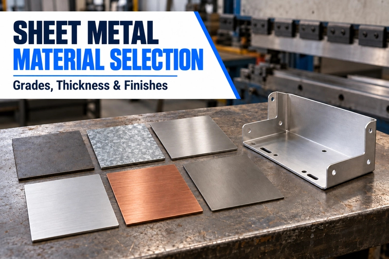
Increasing thickness is one option. Shortening the reach, adding a flange or changing the fastening positions may also help. Recheck weight, assembly space and manufacturability after each change. For a broader comparison, see our material selection guide for custom sheet metal projects.
Check Holes, Flanges and Connections Together
Match Hole Design to Its Function
Determine whether a hole provides bolt clearance, precise location or installation adjustment before selecting a round hole, slot or other locating feature. Slots allow adjustment, but the design must also hold its position after tightening and carry the actual loads at the connection.
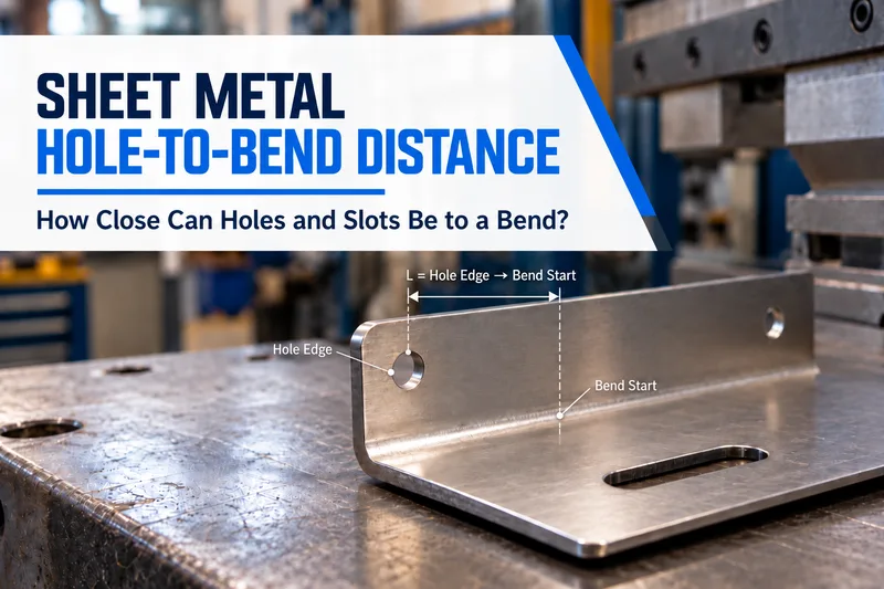
Forming can distort holes or shift their positions near a bend. Consider the material, thickness, actual bend radius and tooling when deciding whether to move a hole, add relief or machine a critical hole after forming. Our hole-to-bend distance guide explains these considerations. A fixed thickness ratio should not be applied to every material and machine.
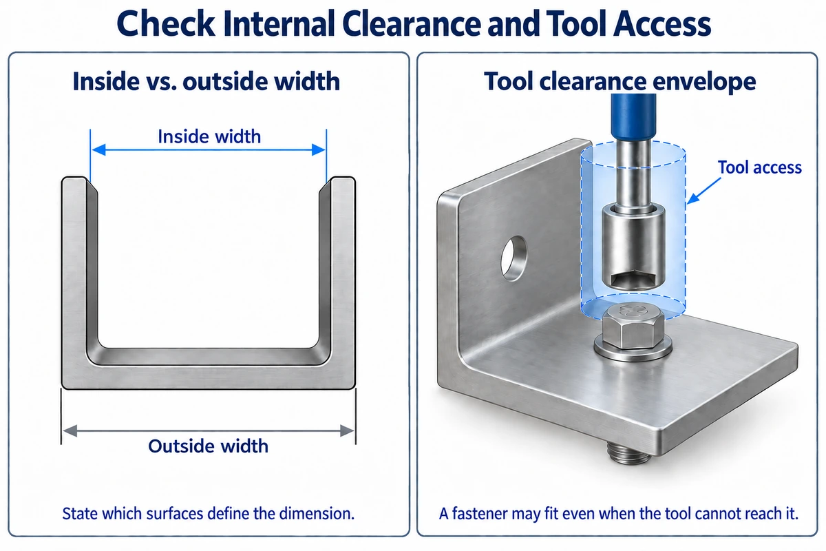
Check whether fasteners can be fitted and tightened. Space for a bolt in the model does not establish access for a nut or a turning tool. Allow for bolt heads, washers, nearby parts and the direction of assembly and removal.
Check Flange Length and Bend Sequence
A flange that is too short may not be supported reliably on the die. In U brackets, hat brackets and other parts with multiple bends, a formed wall may collide with the tooling during the next bend or prevent the part from being removed.
SendCutSend's sheet metal bending design guidance illustrates interference caused by long return flanges. The issue depends on the actual forming space. Its machine dimensions and ratios should not be treated as universal requirements for all fabricators.
For a U bracket, distinguish internal width, external width and sheet thickness. If another part fits inside, specify the required clear space and fit rather than relying only on an external dimension that could be misinterpreted.
Match Connections to Thin Sheet
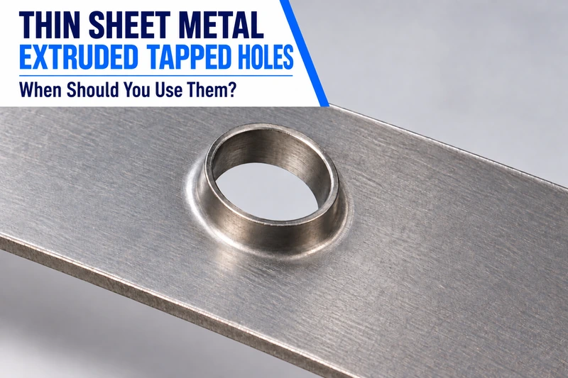
Connections may use bolts, suitable threaded features, self-clinching fasteners or welding. Directly tapping thin sheet requires consideration of thread size, actual thread engagement and service conditions. Where appropriate, compare extruded and tapped holes with other fastening options.
For self-clinching fasteners, check the installation hole, edge distance and other requirements for the specific part number, along with the installation and finishing sequence. PEM's installation guidance warns against treating these mounting holes like ordinary cut edges when deburring, because removing material around the hole can affect the clinched connection.
Welding can join separate pieces or add reinforcement. Account for weld location, welding access and distortion that could affect the final assembly. If a component must be replaced later, its connection must also allow the required removal.
Match the Manufacturing Route to Geometry and Quantity
A typical bent bracket starts as a flat blank with the necessary holes and cutouts, then is formed. Some designs also require joining, threading or other secondary operations. The sequence depends on feature requirements, tool access and finishing. Not every bracket needs punching, bending, welding and coating in a fixed sequence.
Stamping may be worth comparing for stable designs with larger repeat quantities. Evaluate tooling investment, design changes, material utilization and processing time per part together. A single quantity threshold cannot determine which route will always cost less.
A welded assembly can accommodate layouts or structural requirements that are difficult to achieve in one bent piece, but it adds assembly and welding checks. A bracket with threads or locally machined features can retain a sheet metal body with selected secondary operations. Those features do not necessarily require milling the whole part from solid stock.
Compare costs across the complete route. Beyond material, costs may include setup, tooling, additional workholding, finishing and inspection. Identify these influences during design; a specific quotation still depends on the drawing, quantity and acceptance requirements.
Review a Mounting Example
The following hypothetical example illustrates the selection process. It is not a customer order or a report of load capacity or test results.
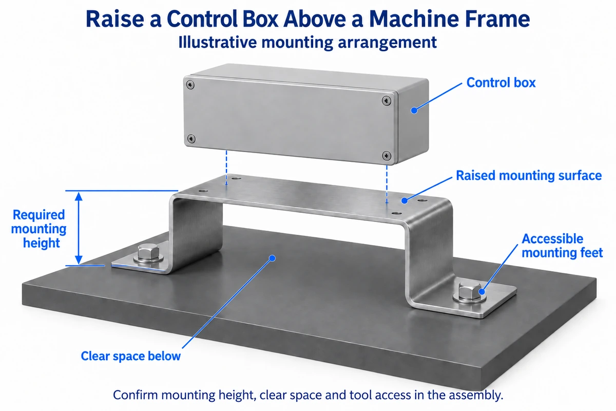
Suppose a control box must be raised above a machine frame. Its mounting surface is parallel to the frame, with a required gap between them. Z brackets or a raised bracket with mounting feet could be initial options. If the box is to be secured from both sides, a U bracket could also be assessed, including its internal width and side-hole positions.
After selecting an initial shape, check the height difference, reach, space needed to insert the box, and access for nuts and tools. If the box blocks a bolt, the hole position, connection or assembly sequence may need to change. If two bends leave insufficient forming space, review the geometry or tooling approach with the fabricator.
The drawing should define the required box position, critical hole spacing and relationship between mounting surfaces. Once material, thickness and finish are established, use samples to check actual assembly and required performance. A model with no interference is not proof that the design has been validated.
Check the Finished Sample in Its Assembly Condition
Sample checks should reflect the intended use. Alongside individual dimensions, confirm that the bracket fits the mating parts after the required forming, joining and finishing operations.
| Check | What to confirm |
|---|---|
| Mounting surfaces and clear space | Angles, offsets, internal space and clearance to adjacent parts |
| Holes and fastening positions | Critical hole spacing after forming, hole shape and fastener installation |
| Assembly and service access | Installation and removal of nuts, tools, cables and covers as intended |
| Finish and fit | Effects on holes, threads and fit clearances, plus any required masking |
| Service performance | Deflection, vibration or other performance under the specified loads and mounting conditions |
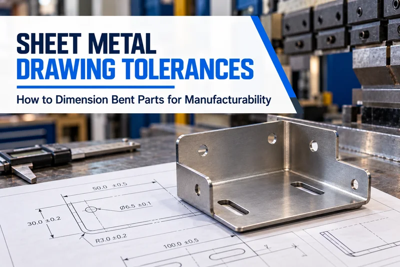
For welded brackets, check critical mounting geometry in the agreed inspection condition. A part may appear correctly positioned in a fixture but fail to fit after release. Our sheet metal drawing tolerances guide covers how to communicate dimensions and datums.
After sample validation, record the actual material and condition, critical dimensions, connections and surface requirements. If material, thickness, process or supplier changes, reassess which checks need to be repeated.
Choose a bracket by establishing the mounting surfaces, loads and allowable deflection, then comparing geometry, material and thickness. Confirm space for holes, fasteners and forming. The finished part must meet assembly and operating requirements, and the drawing, manufacturing plan and sample checks should use those same requirements.
Once the bracket requirements are defined, send Tongyong your drawing or model, material, quantity and operating conditions to discuss manufacturing and inspection requirements. Our custom sheet metal brackets and mounting components page outlines the product range and provides an inquiry route.
FAQ
When Is a Custom Bracket Needed Instead of a Standard Part?
If a standard bracket meets the dimensional, material, finish and performance requirements, a different appearance alone is usually not a reason to customize it. Consider a custom design when hole positions, mounting height or available space do not match, or when several connection functions can be combined in one part. A standard part's rated performance must also match the actual installation conditions.
How Can the Load Capacity of a Custom Bracket Be Assessed?
An L or U shape, or sheet thickness alone, cannot establish a load rating. Define load magnitude, direction and position, fastening conditions, allowable deflection, and any vibration or impact. Then assess the material and structure together. Where load validation is required, calculations or tests need agreed mounting and loading conditions, with the limits of each assessment clearly defined.
What Information Is Needed to Quote from a Hand Sketch?
A sketch can support an initial discussion. Identify whether main dimensions are internal or external, show mounting-hole positions, and describe mating parts or required clear space. Include quantity, any selected material and thickness, finish requirements and operating environment. Mark undecided items for discussion. Confirm complete dimensions, tolerances and acceptance requirements before finalizing the quote and production; do not infer finished dimensions from a photo's proportions alone.
Is a 2D Drawing Still Needed with a 3D Model?
A 3D model communicates geometry and helps review space. A 2D drawing brings together critical dimensions, tolerances, material condition and surface requirements. Providing both is generally advisable. If another data-delivery method contains the complete technical requirements, agree on it with the manufacturer and inspection team beforehand. Both sides need to understand how the finished part will be accepted, beyond being able to open the model.