Correct Parts Before Welding Do Not Always Mean a Correct Final Assembly
Case Note: This representative case is based on our manufacturing experience with similar welded brackets for robotic and industrial automation equipment. Certain project details have been anonymized or adjusted for confidentiality.
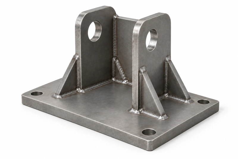
A mounting bracket used in robotic or automation equipment may connect a machine base, actuator, sensor assembly, or other structural components. For this type of weldment, accurately cut plates are only the starting point.
The more important question is whether the mounting surface, hole pattern, side plates, and reinforcing features still line up after welding, cooling, and fixture release.
For this project, we therefore worked backward from the final mounting relationship rather than treating each plate as an isolated part.
Project Overview
| Item | Project Detail |
|---|---|
| Product | Robotic equipment welded mounting bracket |
| Application | Robotics and industrial automation equipment |
| Main Material | Q235B carbon steel |
| Main Plate Thickness | Approx. 6 mm |
| Gusset Thickness | Approx. 5 mm |
| Main Processes | Laser cutting, forming or welded assembly, welding, post-weld inspection, secondary machining where required, surface finishing |
| Manufacturing Focus | Weld distortion, mounting datums, hole relationships, mounting-surface condition, post-weld dimensional verification |
The Assembly Problem
The individual plates could meet their drawing dimensions after laser cutting and forming, while the complete bracket could still move out of alignment during welding.
The reason was not an incorrect cut part. Localized heating and cooling caused weld shrinkage, and the effects of several welds could accumulate across the assembly. If the mounting surface or side plates moved, holes that were correct before welding could end up out of position relative to the equipment they were supposed to fit.
That meant the bracket had to be evaluated as a weldment, not simply as a collection of acceptable sheet-metal parts.
Welding sequence, restraint, and heat input can all affect the final geometry of a welded assembly. These are also common areas addressed in published distortion-control guidance from TWI and ESAB.
How We Set Up the Weldment
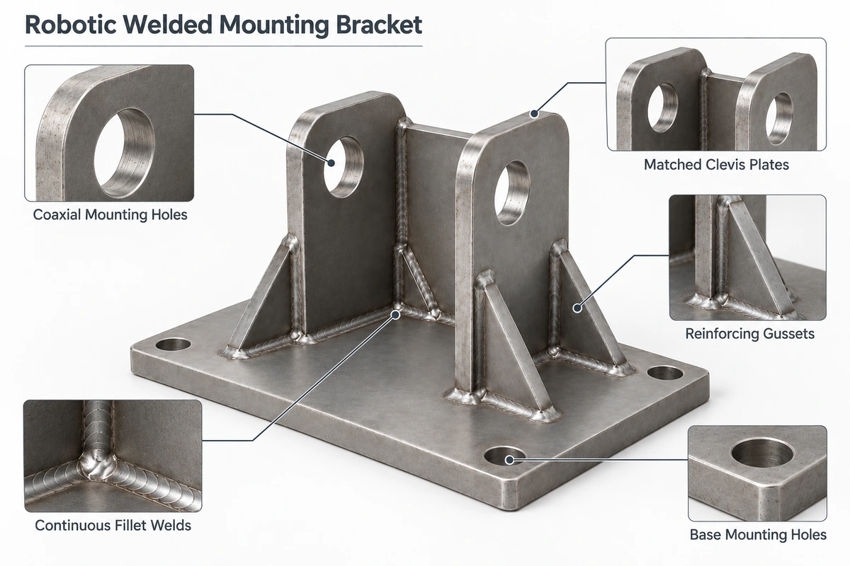
Before welding, we identified the features that mattered most to installation: the primary mounting surface, critical locating or fastening holes, and the side plates or gussets that could influence the final assembly space.
The main formed body or primary welded subassembly was located first. Gussets and secondary welded features were then positioned around that relationship.
The fixture was designed around the mounting relationship, not simply around holding the parts in place.
Tack locations and welding sequence were considered together with the fixture setup. The objective was to keep the functional geometry as stable as practical while avoiding unnecessary heat buildup on one side of the bracket.
Depending on the actual geometry, this could involve balanced, segmented, back-step, or other controlled welding sequences. The sequence depended on the bracket itself and on where the critical mounting features were located.
What We Checked After Welding
The bracket was not accepted just because the welds looked consistent.
After cooling and fixture release, we checked the features that would affect installation:
- mounting-surface condition;
- relationship between critical mounting holes;
- position of the side plates relative to the mounting datum;
- angular or dimensional movement that could interfere with assembly.
This free-state inspection matters because a fixture can restrain movement during welding without guaranteeing the final released geometry.
Would the finished bracket still fit the equipment the way the drawing intended?
That was more important than evaluating the weld appearance alone.
When Post-Weld Machining Was Needed
Not every hole or mounting surface required machining after welding.
Features with less demanding positional requirements could often be completed earlier in the fabrication process. But where a locating hole pattern or mounting surface had a tighter relationship to the final welded datum, we could leave machining allowance and finish those critical areas after welding.
This decision was made from the drawing and the functional requirements of the part.
Post-weld machining was therefore treated as a selective operation, not as a standard step for every welded mounting bracket.
After any required straightening or secondary machining, the bracket could proceed to surface finishing and final inspection.
The final check focused on whether the mounting surface, hole pattern, and overall bracket geometry still worked together as intended.
Customer Value
For this type of robotic welded bracket, the manufacturing challenge is not welding by itself.
The real work is coordinating plate geometry, fixture setup, weld sequence, post-weld movement, and the final mounting interfaces as one manufacturing problem.
By defining the functional datums before fabrication and checking the bracket again after fixture release, problems are more likely to be found before coating or before the part reaches the customer’s assembly line.
That helps reduce the risk of:
- mounting holes no longer matching the equipment;
- warped mounting surfaces;
- rework after finishing;
- drilling or adjustment during final equipment assembly.
| Need a Custom Welded Bracket for Robotic or Industrial Equipment? If you are developing a robotic equipment mounting bracket, welded structural component, or other industrial equipment support, send us your 2D drawing, 3D model, material, critical mounting interfaces, surface-finish requirements, and quantities. We can review manufacturability, weldment structure, functional datums, post-weld inspection requirements, and whether any critical holes or mounting surfaces should be finished after welding. Discuss Your Project |
FAQ
How do you control weld distortion in a steel mounting bracket?
There is no single control method for every bracket. The approach depends on the part geometry, weld locations, stiffness, and the features that must remain aligned. Typical controls can include fixture positioning, tack sequence, balanced or segmented welding, and avoiding unnecessary weld volume. The actual sequence should be selected for the specific weldment rather than copied from a standard pattern.
Should critical mounting holes be finished before or after welding?
It depends on how sensitive the hole position is to weld distortion. Less critical holes can often be completed before welding. For a hole pattern that must maintain a tighter relationship to the finished mounting datum, machining allowance may be left so the feature can be finished after welding.
Why should a welded bracket be inspected after it is removed from the fixture?
Because the fixture controls the part while it is restrained. Once the bracket is released, residual stress may allow a small amount of movement. Critical mounting surfaces and hole relationships are therefore more meaningful when checked in the bracket's free state.
Can a mounting surface and hole pattern be inspected as one functional relationship?
Yes—when the drawing and assembly function define them that way. If the hole pattern is located from a mounting surface or another specified datum, the inspection method should reflect that relationship rather than treating every feature as an unrelated dimension.
What information should be included in an RFQ for a custom welded bracket?
A 2D drawing or 3D model is the best starting point. It is also useful to identify the material, quantity, surface finish, critical mounting interfaces, and any important datums, positional tolerances, weld symbols, or CTQs. If the design is still preliminary, the main mounting relationship and basic dimensions are enough for an initial manufacturability review.